
The rock bolt torque tension relationship describes how applied turning effort relates to axial force within a particular assembly. A torque reading can look acceptable while actual tension differs because friction and contact conditions changed. Request paired measurements on identified bolt hardware before adopting a field conversion. This article defines that calibration task without supplying installation torque values.
1. What does a torque reading actually measure?
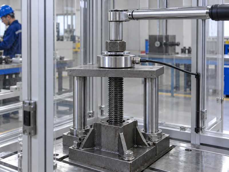
A torque reading measures turning moment at the measurement location, rather than directly measuring bolt tension. The rock bolt torque tension relationship depends on how that moment passes through threads and bearing contacts. Calibration connects those observations for a defined arrangement.
Separate input from measured response
Start with paired observations. Turning a nut involves thread friction, bearing friction, and mechanical deformation. Only an appropriate assembly-specific calibration can support a proposed torque-to-force relationship. Historical government rock-reinforcement research discusses these friction losses, but it supplies no current universal setting for your purchased system.
- Identify where torque is measured within the drive arrangement.
- Measure axial force independently during calibration.
- Record whether values come from tightening, loosening, or a static check.
Measurement definition
Use bolt-family information for naming context, then obtain assembly-specific evidence. Ask the test provider to describe every reported quantity.
| Quantity | Physical meaning | Required qualification |
|---|---|---|
| Torque | Applied turning moment | Measurement location and mode |
| Axial force | Measured tensile reaction | Independent measurement arrangement |
| Conversion | Relationship between paired values | Defined assembly and condition |
Key takeaway: keep torque and tension separately labeled. Their units and measurement methods should never disappear behind a shared pass column.
2. Which components must remain matched?
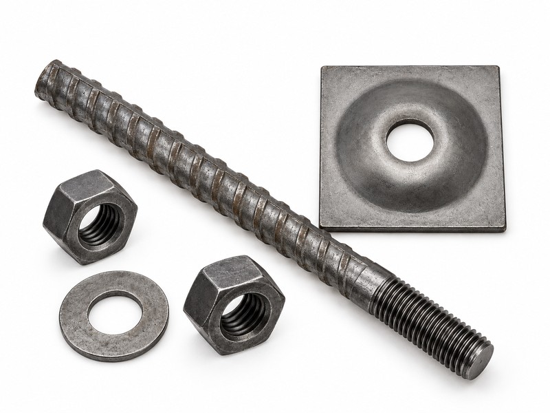
Components must match the assembly covered by calibration, including threads, nut, washer, plate, and relevant anchorage arrangement. A change at any contact interface may alter results. Matching nominal diameter alone provides incomplete identification.
During tightening, nut rotation engages threads while its bearing face reacts against the washer or plate. Those contacts create separate friction interfaces. A substituted washer can change that contact arrangement even when bolt and nut remain unchanged.
Freeze the assembly description
List every loaded contact. Record drawing revisions, component sources, surface finish, and any specified washer arrangement. Describe which parts rotate during tightening and which provide reaction. Mixed hardware needs its own review, especially when a substituted nut or washer changes contact geometry without changing the package label.
- Record bolt and nut thread identification.
- Identify washer orientation and bearing surfaces.
- Retain component lot information for tested specimens.
Assembly identity record
Include actual bearing plates within the relevant calibration description. Ask suppliers to confirm which substitutions invalidate an existing relationship.
| Component | Identity evidence | Change requiring review |
|---|---|---|
| Bolt and nut | Drawings and thread details | Different thread or finish |
| Washer | Geometry and orientation | Different bearing interface |
| Plate or reaction seat | Relevant contact arrangement | Different seating behavior |
Key takeaway: calibrate an identified assembly. A generic chart cannot resolve undocumented differences among components from separate orders.
3. Why must friction conditions be recorded?
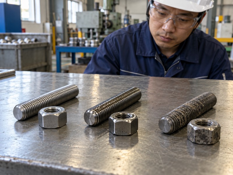
Friction conditions need recording because applied torque can produce different tension when thread or bearing resistance changes. Surface treatment, contamination, corrosion, and lubrication may affect those interfaces. Their effects require evidence for your particular assembly.
Describe the tested condition plainly
Keep surface condition specific. Terms such as standard finish or normal lubrication leave room for different interpretations. State what was applied, where it was applied, and which parts arrived in that condition. Do not add lubricant to installed support hardware based on a generic torque discussion.
- Photograph representative threads and bearing faces before testing.
- Record cleaning and lubrication procedures used for specimens.
- Separate new, reused, damaged, or visibly altered components.
Friction-condition review
Ask your accessory supplier for the supplied condition and applicable handling instructions. Carry that description into calibration records.
| Interface condition | Record needed | Transfer concern |
|---|---|---|
| Lubricated | Material and application location | Different friction response |
| Coated | Specified finish identity | Changed contact behavior |
| Contaminated or damaged | Condition photographs | Unrepresentative calibration group |
Key takeaway: treat friction condition as part of assembly identity. Review changes before using an earlier conversion relationship.
4. How should paired measurements be collected?
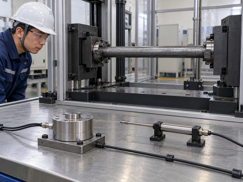
Paired measurements should record torque and independently measured axial force during an approved calibration procedure. Both readings need identifiable timing and measurement points. The test laboratory should select a suitable arrangement and operating sequence.
Seating movement and subsequent axial loading need distinct observation points. Rotation while contact surfaces settle can produce a different response from later tightening. Ask how the calibration procedure recognizes and reports that transition.
Request a documented loading sequence
Read both channels together. Ask how instrument alignment, reaction stiffness, seating, and acquisition timing are controlled. Record whether reported torque represents a peak, moving average, or another defined quantity. A manually copied maximum from one instrument may not correspond with a maximum from another.
- Preserve synchronized records where the procedure supports them.
- Identify equipment calibration and measurement ranges.
- Document aborted tests, seating changes, and unusual observations.
Paired-data checklist
For mechanically anchored configurations, ask how anchorage behavior enters the test arrangement. Do not turn a bench calibration into a field setting without engineering review.
| Data field | Required definition | Buyer question |
|---|---|---|
| Torque value | Sampling and reporting rule | Which moment does it represent? |
| Force value | Independent sensor and timing | Does it match that torque observation? |
| Sequence state | Seating or loading stage | Are observations comparable? |
Key takeaway: approve data definitions before testing. Paired numbers need a common physical event and a traceable measurement arrangement.
5. What should a calibration curve disclose?
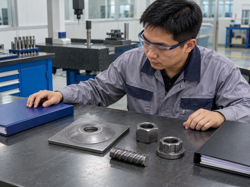
A calibration curve should disclose the tested assembly, observation range, data distribution, and any fitted relationship. A smooth line alone hides specimen variation. The rock bolt torque tension relationship should remain bounded by actual calibration evidence.
Examine observations before fitting
Keep the scatter visible. Ask for individual paired results and the method used to derive any fitted line. Confirm whether separate assembly conditions were combined. A reviewer should see how much results differ within a group before deciding whether a proposed field target provides sufficient control.
- Show individual specimens and their hardware identities.
- Identify the tested range without extrapolating beyond it.
- Request an explanation for excluded observations.
Curve-review fields
Keep installed support context separate from bench data. Ask your engineer to determine whether calibration uncertainty suits the intended use.
| Curve element | Evidence | Review concern |
|---|---|---|
| Individual points | Paired observations | Hidden variability |
| Fitted relationship | Stated calculation method | Unsupported averaging |
| Valid range | Actual observation interval | Extrapolated force estimates |
Key takeaway: approve evidence and limits together. A line drawn beyond measured conditions should not become a procurement promise.
6. How do tools change field transfer?
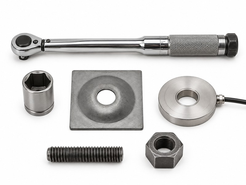
Tools can change field transfer through measurement mode, drive arrangement, operating sequence, and control behavior. A hand wrench calibration does not automatically establish settings for another tightening system. Ask how the proposed field tool relates to the calibrated arrangement.
Record the complete drive arrangement
Include the adapters. List torque instrument location, sockets, extensions, and relevant drive components. Specify whether calibration represents continuous tightening, an interrupted sequence, or a later check. Tool condition and operating procedure belong in the transfer review alongside hardware identity.
- Record tool model, control mode, and calibration status.
- Identify adapters included in testing.
- Ask which operating changes require another comparison.
Tool-transfer review
A hollow-bar assembly may involve different components and operating tasks. Do not transfer a relationship merely because both systems use a nut.
| Tool detail | Record | Reason for review |
|---|---|---|
| Measurement mode | Defined tightening or checking method | Different observation meaning |
| Drive components | Actual tested arrangement | Changed torque transmission |
| Tool control | Settings and operating sequence | Different application behavior |
Key takeaway: tie field instructions to identified equipment. Hardware calibration and tool setup need a documented connection.
7. Can a later torque check recover original tension?
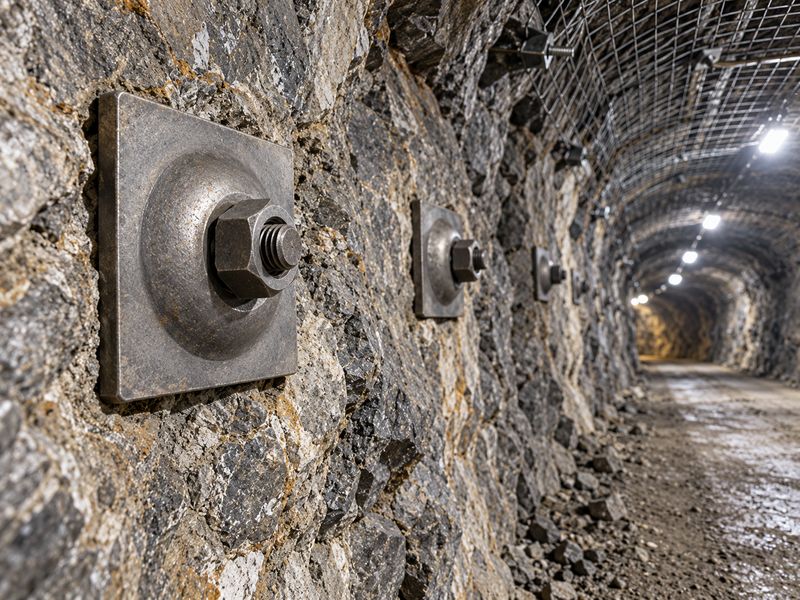
A later torque check cannot automatically recover original installed tension because contact state and loading history may have changed. Breakaway, loosening, and continuing-tightening observations describe different actions. Their interpretation requires a method approved for that assembly.
Separate checks from installation records
Name the check you requested. Avoid a report field labeled torque verified without describing what the operator did. A check can disturb hardware or produce an observation different from initial tightening torque. Site personnel need an approved procedure and authorization before manipulating installed components.
- Identify the check direction and stopping rule.
- Record elapsed time and known changes since installation.
- Preserve original installation measurements alongside later observations.
Check interpretation
Keep pull-test evidence separately identified if requested for another engineering purpose. Neither record should be relabeled as the other.
| Observation | What it records | What remains unresolved |
|---|---|---|
| Installation torque | Original tightening operation | Later tension state |
| Breakaway observation | Moment initiating movement | Original tightening relationship |
| Mechanical force measurement | Response within its setup | Applicability beyond tested condition |
Key takeaway: write the check method into inspection records. An unlabeled torque number cannot reconstruct a complete tension history.
8. When should calibration be reviewed again?
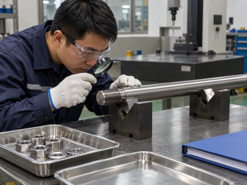
Review calibration whenever assembly identity, surface condition, equipment, or the proposed operating method changes. A review determines whether existing evidence remains applicable. It does not always require the same response for every change.
Establish change triggers in advance
Make substitutions visible. Procurement substitutions can reach site before engineering teams see revised drawings. Require notification when nuts, plates, coatings, or lubrication change. Ask the calibration owner to document whether each change remains covered, needs additional comparison, or requires a new approved relationship.
- Link purchase revisions with calibration applicability.
- Quarantine unidentified mixed components pending review.
- Record approval before revised field instructions are issued.
Change-control matrix
Assign a calibration owner who can review supplier changes promptly. Include affected inventory and existing site instructions in that review.
| Change | Initial action | Closure record |
|---|---|---|
| Component substitution | Compare assembly identity | Approved applicability decision |
| Surface-condition change | Review friction assumptions | Qualified evidence or new testing |
| Tool or method change | Check transfer basis | Revised operating instruction |
Key takeaway: attach calibration to a controlled configuration. Document why evidence remains applicable after a change.
9. What makes a calibration report reviewable?
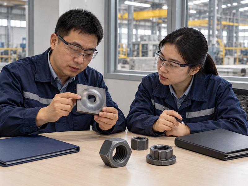
A reviewable report connects specimen identities, measurement procedures, individual observations, uncertainty, and applicability limits. It should allow a qualified reader to follow the proposed conversion without guessing. A certificate bearing one representative torque value cannot do that.
Build the evidence chain
Trace one specimen completely. Start with its lot identification and follow assembly preparation, instrument records, paired results, and final interpretation. Confirm that summary tables agree with underlying files. Ask the laboratory to explain unusual behavior rather than silently removing inconvenient observations.
- Require traceable specimen and component identification.
- Retain raw records and calculation revisions.
- List deviations, limitations, and reviewer approval.
Report-completeness table
Use this table during technical review rather than relying on document thickness. Return incomplete relationships for clarification before field adoption.
| Evidence layer | Required connection | Review outcome |
|---|---|---|
| Specimen | Components and condition | Defined configuration |
| Measurement | Equipment and sequence | Traceable paired data |
| Interpretation | Fit, spread, and limits | Qualified field-transfer decision |
Key takeaway: review the chain from hardware to conclusion. Missing links should remain open actions in your procurement record.
10. What should your calibration request specify?
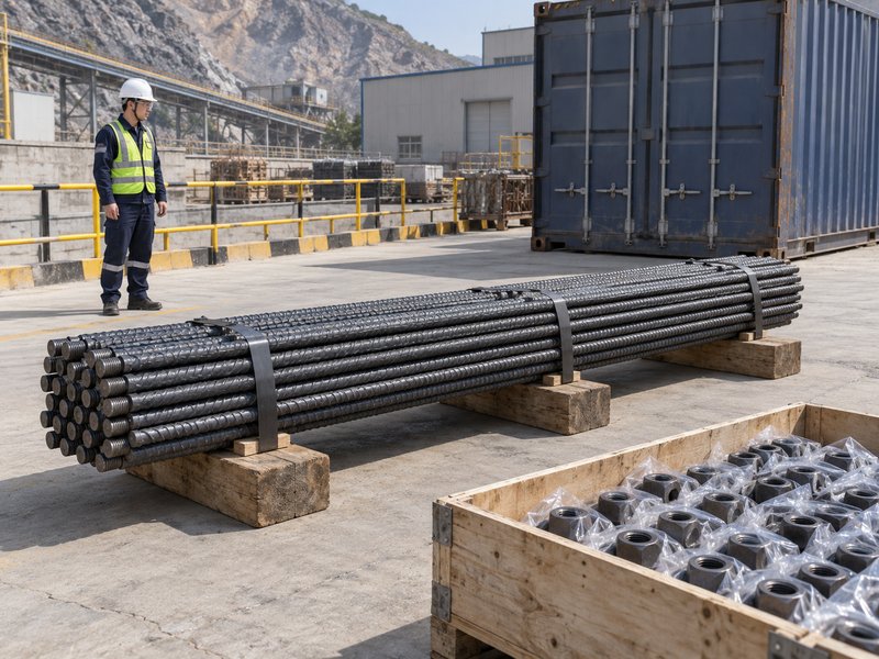
Your calibration request should specify the assembly, intended field method, independent force measurement, data deliverables, and review responsibility. The rock bolt torque tension relationship needs those boundaries before anyone proposes operating values. Have qualified project personnel approve how results will be used.
Send hardware and conditions together
Make the request reproducible. Include drawings, sample identities, supplied surface condition, and proposed tools. Ask the laboratory to propose specimen numbers and measurement procedures appropriate for your decision. Do not choose an unsupported universal sample count or torque factor from an unrelated chart.
- State whether your goal concerns installation control or another defined check.
- Request individual paired observations and a qualified relationship.
- Require a written statement of applicable conditions and change triggers.
Close the procurement interface
| Closure check | Action to retain |
|---|---|
| 1 | State whether your goal concerns installation control or another defined check. |
| 2 | Request individual paired observations and a qualified relationship. |
| 3 | Require a written statement of applicable conditions and change triggers. |
Identify who supplies matched components and who owns engineering approval. For a hardware discussion, contact us with your assembly drawings and proposed calibration scope. Request product-specific evidence before accepting any torque setting for use underground.
Q1: Can I use a generic torque chart for rock bolts? Only with a justified engineering basis. Generic values may represent different threads, friction conditions, components, or measurement methods.
Q2: How do I know whether lubrication changes the relationship? Ask for matched test evidence. Record lubricant identity and application location before comparing results.
Q3: Can a higher torque always mean higher tension? No universal conclusion follows. Changed friction, seating, or component behavior can alter that relationship.
Q4: What’s the best way to report calibration scatter? Retain individual paired observations and their conditions. Ask the calibration engineer to explain variation and its practical limits.
Q5: Should substituted nuts trigger a review? Yes. Their thread and bearing interfaces form part of the calibrated assembly, even when nominal size remains unchanged.