
A rock bolt pull out test procedure applies a controlled axial load to an installed bolt or anchor while recording movement. Engineers use the result to check installation quality, bond behavior, proof-load response, or ultimate resistance, depending on the test type. The test is only meaningful when its purpose, load schedule, acceptance criteria, equipment, and reporting method are defined before the jack is connected.
This eight-step field guide explains how to prepare, load, measure, interpret, and document the test. However, it does not supply a universal test load or pass/fail movement because those values must come from the approved design, governing standard, and project specification.
1. Define the rock bolt pull out test procedure
First decide what the test is intended to prove. A sacrificial suitability or performance test may explore the ground-grout interface and movement over several load cycles. A production proof test checks an installed anchor against a specified test load. A destructive test seeks a failure mechanism and should not be performed on a support element that must remain in service.
Terminology varies among soil nails, rock bolts, dowels, and prestressed anchors. Therefore, name the element, anchorage system, free length if any, bonded length, design load, test type, and acceptance clause on the test sheet. The FHWA Ground Anchors and Anchored Systems manual clearly separates performance, proof, and creep tests and shows how their loading schedules and interpretations differ.
| Test type | Main purpose | Typical use | Required decision |
|---|---|---|---|
| Suitability or performance | Characterize load-movement behavior | Trial or representative anchors | Confirm design and installation method |
| Proof | Check an installed production element | Specified sample or production population | Accept, investigate, or remediate |
| Creep | Measure time-dependent movement | Ground or anchor conditions identified by the design | Assess long-term suitability |
| Destructive | Identify ultimate response or failure mode | Sacrificial elements only | Establish or confirm design resistance |
2. Review records before testing
A pull test starts with the installation record. Confirm bolt ID, location, orientation, bar and coupler type, hole diameter and depth, resin or grout batch, installation time, cure time, groundwater observations, plate condition, and any drilling interruption. If these details are missing, the result may identify a problem without revealing its cause.
Verify that the required curing period has elapsed under the actual site temperature. Do not substitute a generic “24-hour” rule for the approved resin or grout data. If the test concerns a self-drilling or grouted system, compare the grouting record with the project quality plan. The FHWA Soil Nail Walls Reference Manual provides a useful model for connecting installation records, grout control, verification tests, proof tests, and acceptance criteria.
3. Calibrate the rock bolt pull out test equipment
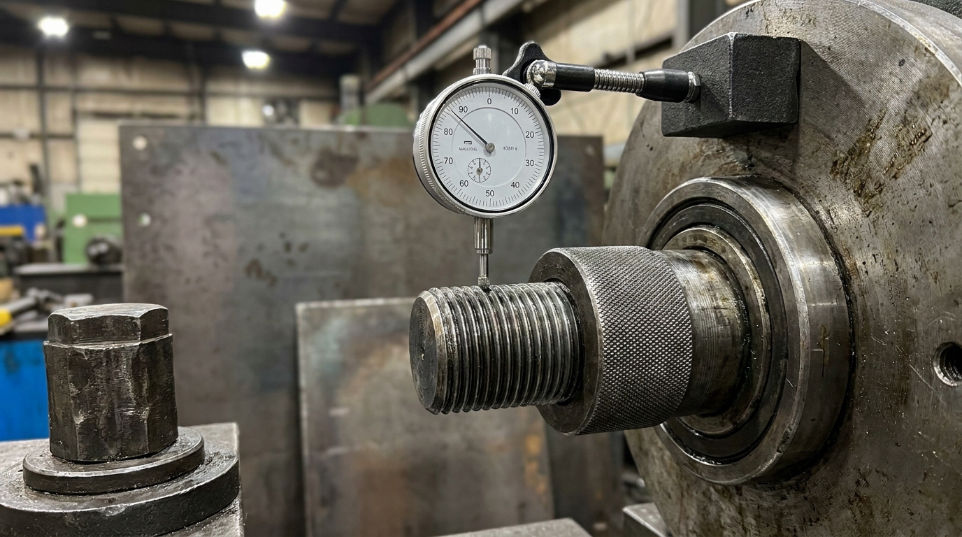
Use a jack, pump, pressure gauge or load cell, displacement gauge, reaction frame, pull head, adapters, hoses, and couplers rated for the planned load and geometry. Next, check each item’s identification and calibration status. A pressure reading is not automatically the force at the bolt; the jack-pump-gauge assembly needs a current conversion relationship.
Where crews use a load cell, keep its readout with the calibrated sensor configuration. The NIST force-transducer calibration program explains how a laboratory can calibrate a transducer and customer readout as one system. That calibration then applies to the paired configuration, which is a useful reminder not to mix sensors and indicators casually.
- Confirm capacity exceeds the highest planned test load with the required margin.
- Check the calibration certificate, range, date, serial number, and configuration.
- Inspect hoses, fittings, seals, threads, cables, and batteries.
- Zero force and displacement channels only after the setup is seated as specified.
- Prepare a backup recording method without changing the calibrated load path.
4. Build an aligned and stable reaction setup
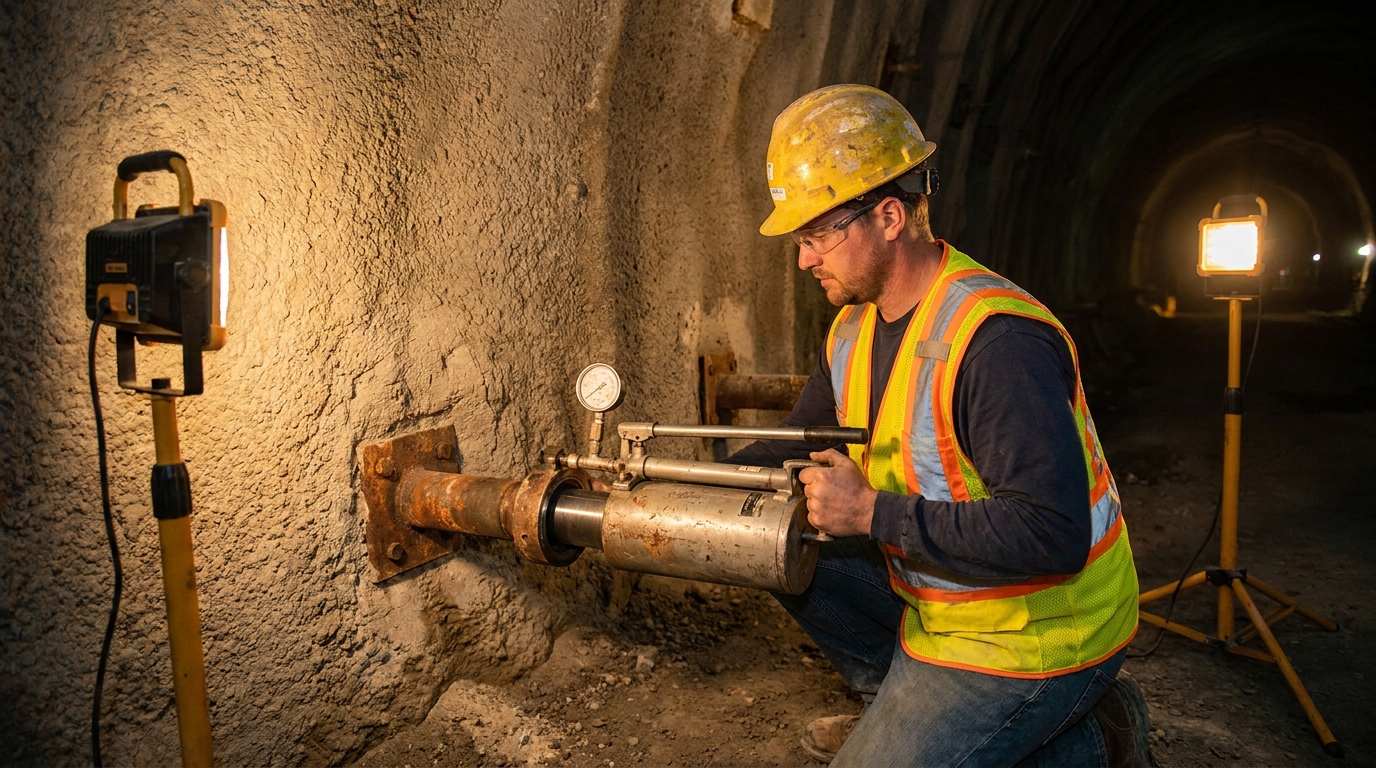
Expose enough sound thread for the pull head, then clean and inspect it. In this part of the rock bolt pull out test procedure, seat the reaction bridge on competent material or a designed bearing arrangement that will not crush, slide, or influence the displacement reference. Align the hydraulic jack with the bolt axis. Off-axis loading introduces bending, side-loads the jack, and can distort the recorded movement.
Mount the displacement gauge on an independent reference frame outside the reaction zone. Its stem should follow the intended movement direction and have enough travel for the complete schedule. Then, photograph the setup from two angles and record any surface preparation or shims.
5. Establish the exclusion zone and communication
Stored energy makes a pull test hazardous. A bolt, adapter, hose, coupling, bearing plate, or reaction component can fail suddenly. Therefore, keep people out of the line of the bolt and away from likely projectile paths. Use barriers, restrained components where specified, remote reading where practical, and one designated person to control loading.
Inspect the work area for loose ground before setting up. The OSHA underground-construction requirements emphasize hazard instruction, communications, mechanical equipment, PPE, ventilation, emergency procedures, and reporting conditions such as ground movement or equipment failure. These controls sit around the test method; they are not replaced by it.
6. Apply the specified rock bolt pull out test load schedule
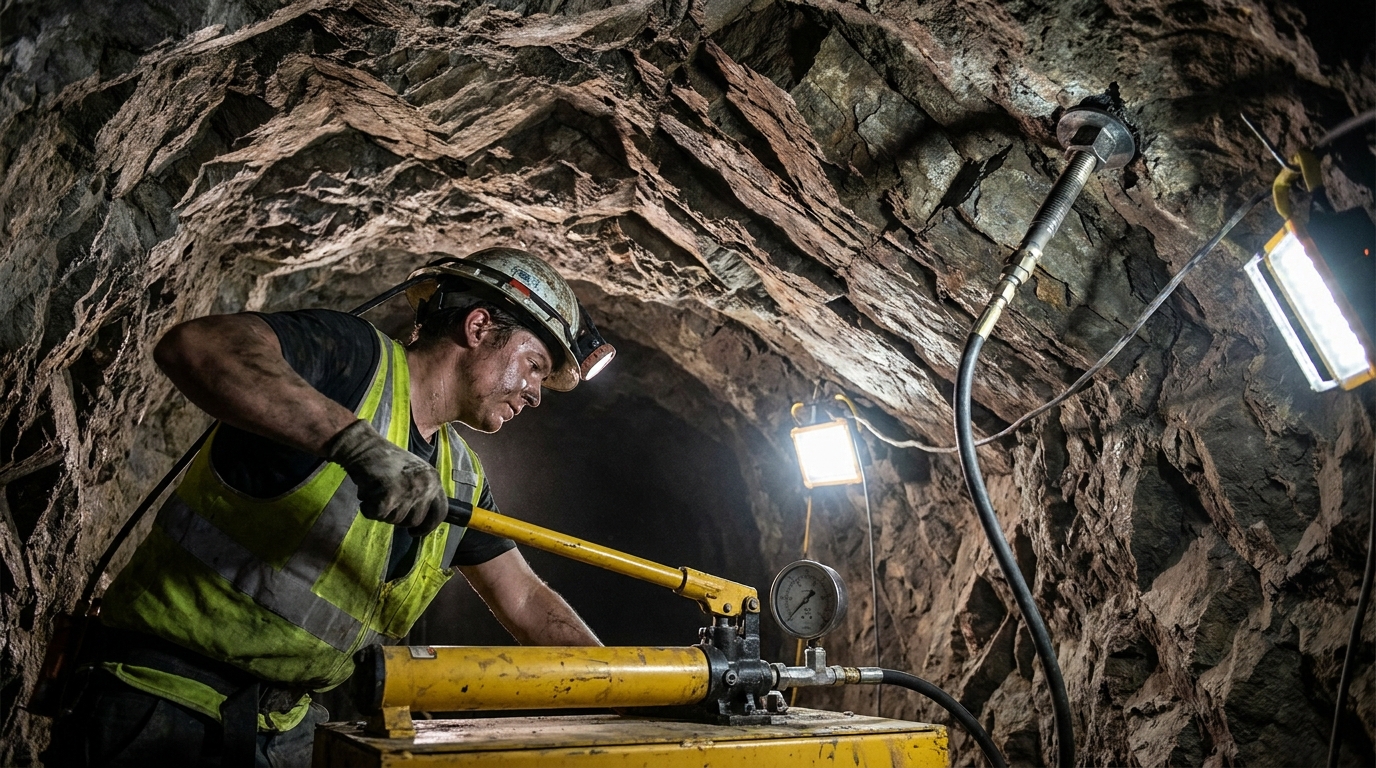
The loading stage of a rock bolt pull out test procedure begins with the specified alignment or seating load. Establish the displacement datum, and then raise load smoothly through the approved increments. At each stage, record force, total movement, time, and observations. Hold each increment for the required period; do not rush a stable reading or invent extra load steps in the field.
If the program includes unloading and reloading, record residual as well as total movement. Stop when the test reaches the approved abort criterion, the setup becomes unstable, the gauge exceeds its safe range, a component leaks or deforms, movement accelerates unexpectedly, or the responsible engineer directs a stop.
| Stage | Record | Field check |
|---|---|---|
| Alignment load | Initial force, datum, time | Seating and axial alignment |
| Each increment | Applied force, total movement, elapsed time | Gauge stability and reaction behavior |
| Hold period | Movement at specified time intervals | Time-dependent movement |
| Unload or lock-off | Residual movement or final lock-off value | Follow the approved sequence |
| Stop event | Load, movement, time, visible or audible signs | Make the area safe before inspection |
7. Interpret the load-movement curve
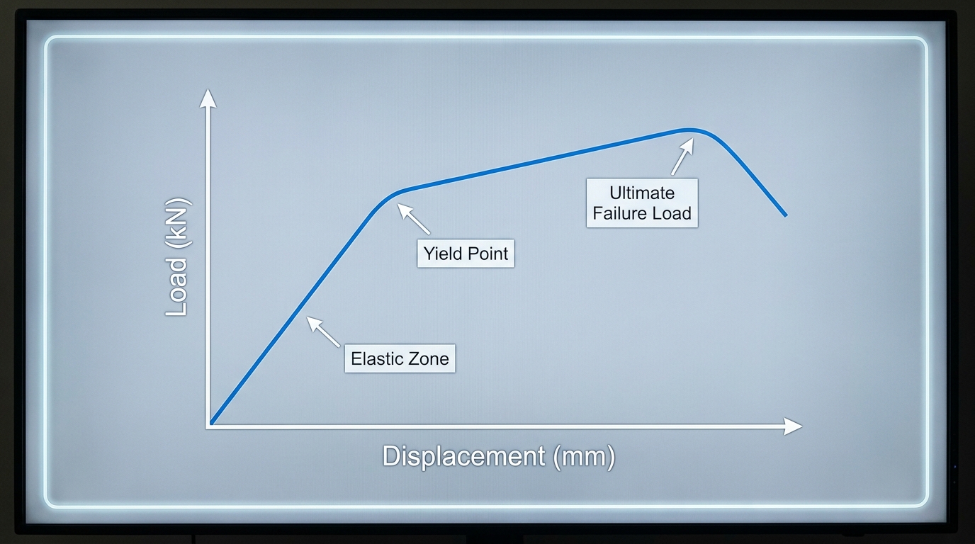
Plot applied load against measured movement and, where relevant, show residual movement or movement versus logarithmic time. A change in slope may reflect seating, steel extension, bond slip, ground deformation, reaction movement, or instrument error. One curve feature rarely identifies the cause by itself.
Compare the result with the acceptance criteria for that exact test type. For a prestressed ground anchor, the FHWA manual checks elastic movement against calculated bounds and evaluates movement during the test-load hold. A local rock-bolt quality test may use a different criterion. Do not borrow proof-test ratios or movement limits from another anchorage system.
- Early nonlinearity: review seating, slack, reaction movement, or early interface response.
- Progressive movement during a hold: compare with the specified creep or movement criterion.
- Sudden load loss: stop and investigate equipment, connection, steel, or bond failure.
- Unexpectedly low movement: confirm that the displacement reference is independent and free to move.
8. Complete the rock bolt pull out test report
The rock bolt pull out test procedure ends with a report that allows another engineer to reconstruct the test. Include the project and location, bolt identification, system details, installation record, cure time, ground conditions, test type, specified schedule, acceptance clause, equipment and calibration IDs, setup photographs, raw readings, plots, observations, deviations, result, reviewer, and corrective action.
Keep raw data as well as the cleaned chart. If you correct a reading, preserve the original and explain the correction. A failed result should trigger the response defined in the quality plan: equipment checks, record review, adjacent tests, investigation, replacement, redesign, or another action authorized by the responsible engineer.
For related installation controls, see our rock bolt installation procedure, the comparison of rock bolts and rock anchors, and the guide to selecting resin capsules for mining rock bolts.
Rock bolt pull out test procedure checklist
- Identify the element, test type, purpose, load schedule, and acceptance clause.
- Review installation, material, curing, and ground-condition records.
- Verify equipment capacity, condition, calibration, and sensor pairing.
- Build an axial reaction setup with an independent displacement reference.
- Establish the exclusion zone and one clear loading command.
- Apply increments and holds exactly as the approved procedure requires.
- Plot and assess all force, movement, and time data against the correct criteria.
- Issue a traceable report and close any corrective action.
Frequently asked questions
Can an in-service rock bolt be tested to failure?
Not if the bolt must continue supporting the excavation. Destructive testing belongs on a sacrificial element or another location specifically approved by the designer. Production supports are normally checked with a defined proof or quality-control test.
How long should grout cure before the test?
Use the minimum age or verified strength required by the approved grout design and project specification. Cement type, proportions, temperature, admixtures, ground water, and required test load all affect the answer.
Can pump pressure be converted directly to bolt load?
Only with the current calibration relationship for the actual jack, gauge, pump, and relevant configuration. Piston area alone may not account for system friction, seating, or configuration effects.
What should I do if the curve looks abnormal?
Stop at the procedure’s abort criterion, secure the area, and check alignment, reaction stability, sensors, connections, installation records, and visible ground response. Let the responsible engineer determine whether to repeat, extend, reject, or investigate the test.
If you need matched bolts, plates, nuts, couplers, or resin systems for an approved test program, send Yongduo Roller the specification and drawings for a component review.