
To secure the right self-drilling rock bolt, start with ground conditions, compatible components, installation controls, and supplier evidence. First, understand the system: it combines drilling, load transfer, and grout delivery in one permanent hollow-bar assembly. In unstable ground, an ordinary bore may close before your crew inserts a solid tendon. As a result, that collapse wastes shifts, grout, and consumables while raising installation risk. By contrast, a self-drilling rock bolt keeps its sacrificial bit and hollow bar in place. Therefore, your team keeps one controlled path from bore start through grouting.
1. Start With the Self-Drilling Rock Bolt System
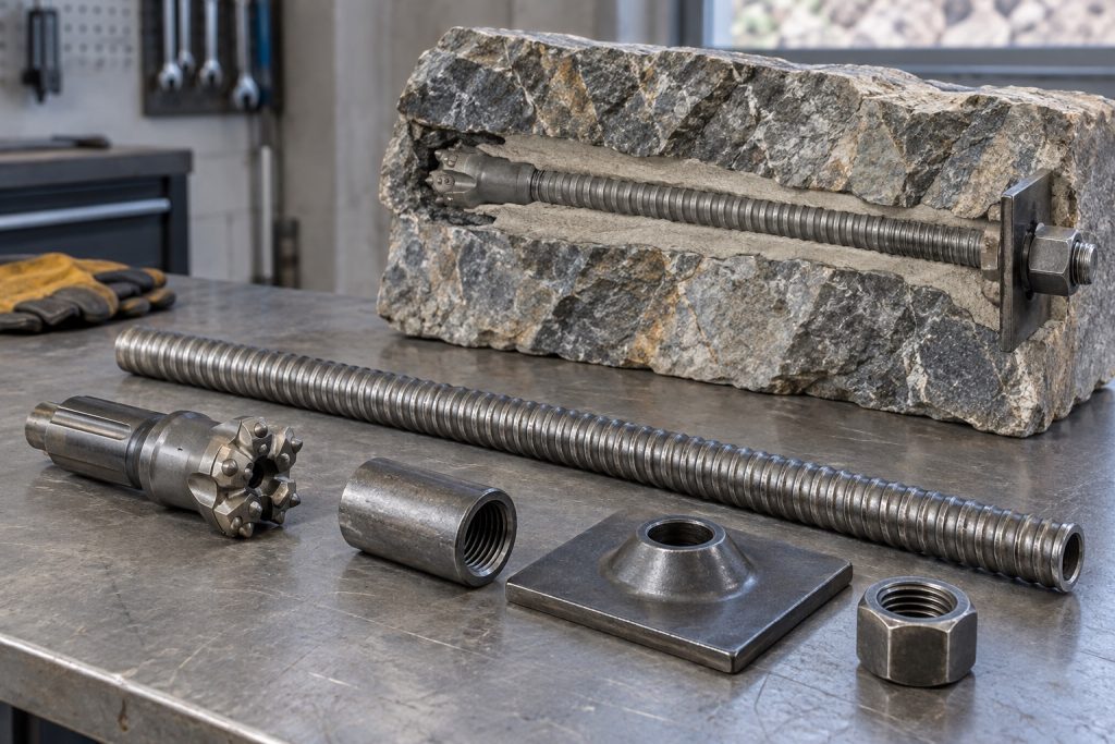
Next, a self-drilling rock bolt is a hollow threaded tendon. It drills its own bore, stays underground, and carries grout through its center. Meanwhile, a sacrificial bit cuts ahead of the bar while external threads accept couplers, plates, and nuts. This layout suits ground that cannot hold an open bore long enough for conventional insertion. In addition, fully threaded lengths let crews cut or couple bars as site geometry changes.
Why does one permanent drill string help?
Start with field reality. For example, one assembly keeps support inside weak ground while drilling continues. Grout also travels through a known path. Therefore, the system stays in place when fresh bore walls would slough before a separate tendon arrives.
- Hollow bar carries load and grout
- Sacrificial bit stays at bore end
- Grout bonds steel with surrounding ground
- Plate and nut spread surface load
| System role | Working element | Site purpose |
|---|---|---|
| Penetration | Sacrificial bit | Opens a path through soil or rock |
| Reinforcement | Hollow bar | Remains as permanent tendon |
| Bond | Cement grout | Transfers load along embedded length |
Therefore, read each row as one connected load path. Key Takeaway: You gain better control when design, drilling, grout, and hardware stay under one system specification.
2. Match Every Self-Drilling Rock Bolt Component
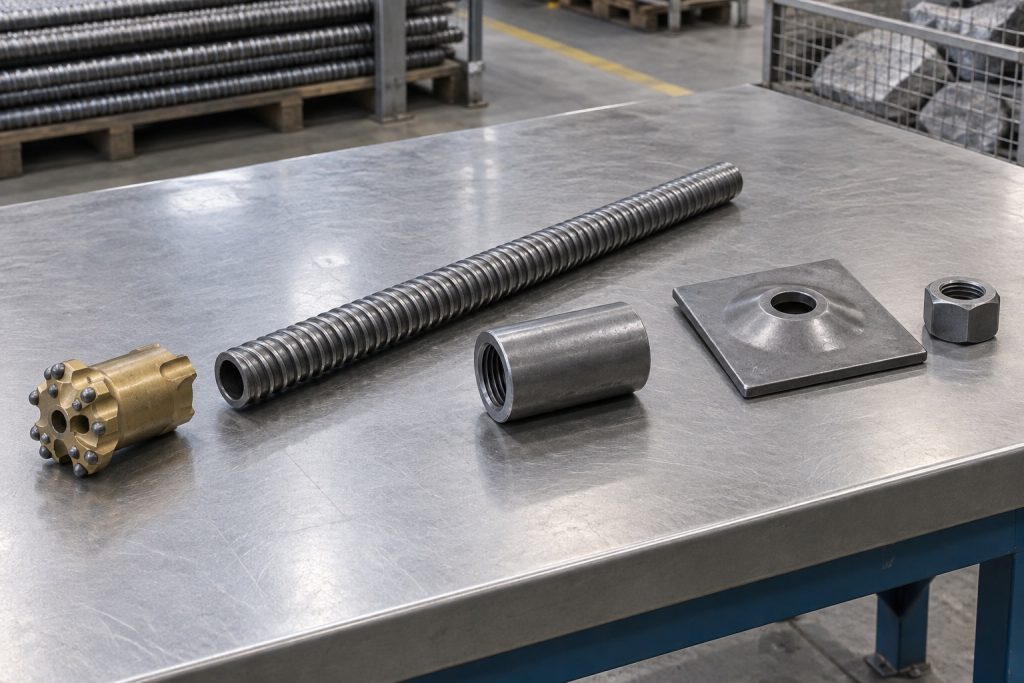
In addition, five core parts make a self-drilling rock bolt work: bit, hollow bar, coupling, bearing plate, and nut. A drill adapter connects this string with rig tooling. At the same time, flushing or grout travels through each aligned bore. Every thread, shoulder, and contact face must match. Otherwise, one poor fit can interrupt energy transfer or grout flow. Finally, the drive adapter helps during installation but does not remain at every finished anchor.
What should you inspect before drilling?
Check the interfaces next. Also confirm that bars seat inside couplers and bits match the thread profile. Then verify that bearing plates and nuts sit square against prepared ground. Finally, check every dimension against approved drawings before material reaches the face.
- Bar bore remains clear from end to end
- Coupler threads run without binding
- Bit ports remain open
- Plate hole and nut seat match bar size
| Component | Pre-use check | Failure avoided |
|---|---|---|
| Bit | Thread fit and open ports | Poor drilling or blocked flushing |
| Coupler | Full engagement | Energy loss or separated joints |
| Plate and nut | Correct seat | Uneven surface load |
This check puts attention on interfaces where field problems often start. Key Takeaway: As a result, a matched assembly protects drilling performance and gives your crew fewer surprises underground.
3. Control Self-Drilling Rock Bolt Installation
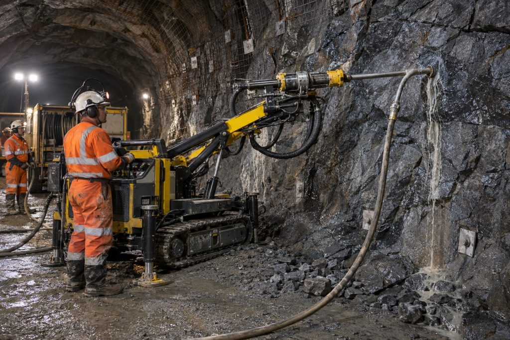
Then, a self-drilling rock bolt drills through its sacrificial bit. Crews extend bars as needed and pump grout through the hollow center. During drilling, your crew follows the planned line and angle. It also monitors penetration, flushing returns, torque, and bore behavior. Afterward, plate and nut installation follows the approved grout and curing sequence. However, unexpected ground response should trigger engineering review before work resumes.
Which installation controls deserve a written record?
Watch what changes at the face. Meanwhile, a practical rock bolt installation procedure records each bore. Therefore, supervisors do not need to rely on memory after a shift. They can also link unusual returns or grout loss with one exact location.
- Mark location, inclination, and planned length
- Record bit and bar references
- Note drilling response and visible returns
- Log grout volume, pressure trend, and interruptions
- Record plate fitting and verification result
| Stage | Crew action | Record kept |
|---|---|---|
| Setout | Confirm location and angle | Bore reference |
| Drill and grout | Monitor response and returns | Installation log |
| Closeout | Fit hardware and verify | Acceptance record |
Use those records to compare installed conditions with design assumptions. Key Takeaway: Consequently, a repeatable log turns hidden work into evidence your engineer and client can review.
4. Plan for Faster Site Production
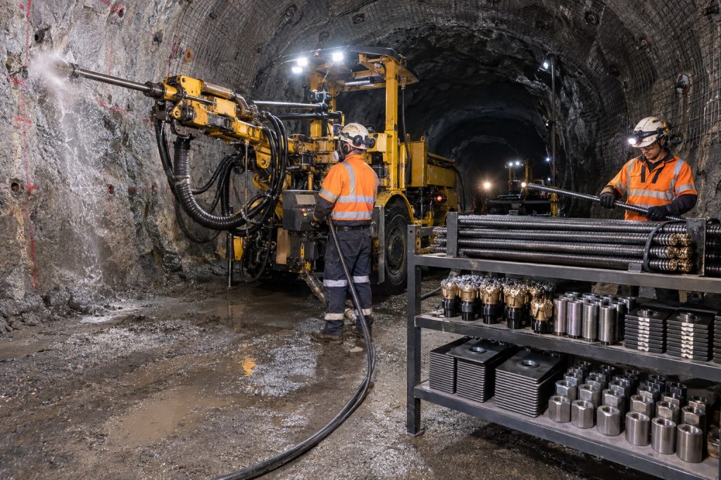
As a result, a self-drilling rock bolt can save site time in collapsing ground. It removes separate casing, tendon insertion, and casing withdrawal stages. Therefore, your crew handles fewer changeovers. The permanent bar also keeps a continuous route for flushing and grout. However, time gains still depend on prepared consumables, suitable rig settings, steady grout supply, and trained operators. Poor staging can erase the advantage even when hardware performs well.
Where do production gains come from?
Look beyond drilling speed. In practice, most gains come from avoiding repeated bore recovery. They also depend on keeping matched parts ready at the work area. Therefore, a balanced cycle measures staging, drilling, coupling, grouting, cleanup, and verification.
- Fewer bore reopening attempts
- Less handling between drilling and anchoring
- Coupled lengths prepared near the rig
- Grout equipment ready before penetration ends
- One inspection record across each installed assembly
| Time driver | Conventional risk | System response |
|---|---|---|
| Bore stability | Hole closes before insertion | Bar remains during drilling |
| Tool changes | More handling stages | One permanent drill string |
| Extension | New bore may be required | Threaded bars can be coupled |
Therefore, review delays by cause before promising a production rate. Key Takeaway: You save time when the system removes unstable-bore recovery steps. Unsupported speed claims do not help planning.
5. Match the System to the Application
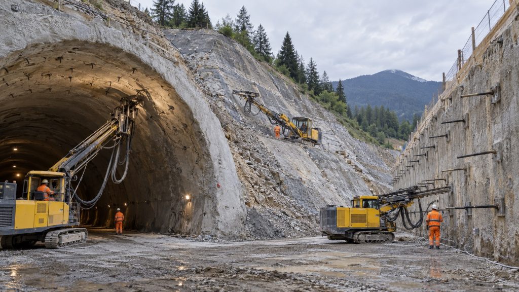
For example, a self-drilling rock bolt can support tunnels, slopes, excavations, retaining structures, and micropile work. These applications often face bore collapse during installation. Engineers must match tendon capacity, bond length, bit, grout, and corrosion protection with ground behavior. For broader design context, consult the FHWA Ground Anchors and Anchored Systems manual. However, your design still needs project-specific analysis. Similar-looking faces can carry different failure mechanisms. Common roles include tension reinforcement, soil nails, grouted anchors, and compression members within designed micropiles.
Which project conditions suit this system?
Match each system with its failure mode. Instead, begin with ground movement and load path rather than product preference. Then your engineer can define whether each tendon works in tension, compression, or both.
- Tunnel crowns with fractured or weathered rock
- Cut slopes where loose bands interrupt rock mass
- Excavation walls needing soil nails
- Retaining structures requiring grouted anchors
- Underpinning zones needing hollow-bar micropiles
| Application | Ground concern | Design focus |
|---|---|---|
| Tunnel | Block release around excavation | Pattern, length, and surface restraint |
| Slope | Sliding along weak layers | Orientation and bond zone |
| Micropile | Load transfer below weak material | Bar capacity and grout body |
That comparison shows why application names cannot replace ground design. Key Takeaway: Therefore, choose this system only when the installation method and load path suit one another.
6. Let Ground Conditions Drive the Choice
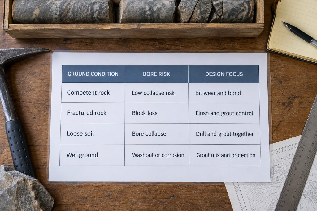
However, ground controls every self-drilling rock bolt choice. It affects the bit face, flushing medium, grout plan, length, and corrosion protection. Competent rock may stress cutting tools. By contrast, fractured rock can lose blocks, loose soil can collapse, and wet ground can alter grout behavior. Therefore, bore logs, groundwater observations, trial installations, and verification results support each adjustment. Changes across a single bore may still require more than one field response.
How should you turn ground data into a selection?
Keep one question in view. For that reason, each observation must change a design or installation choice. Comparisons among rock bolt types should also follow ground behavior. In addition, photo records and bore logs make those changes easier to review across shifts.
- Note fracture spacing and orientation
- Record weathering and abrasive bands
- Map water inflow and grout loss
- Compare penetration and return behavior
- Escalate unexpected changes for engineering review
| Ground response | Field clue | Possible review point |
|---|---|---|
| Blocky rock | Sudden jumps or voids | Bit face and grout take |
| Loose soil | Weak returns or collapse | Flush control and grout sequence |
| Wet zone | Diluted returns or washout | Mix, pressure, and protection |
Use this matrix as a discussion aid, never a substitute for design. Key Takeaway: Therefore, ground observations become useful only after your team connects them with a documented response.
7. Match the Thread, Bit, and Rig
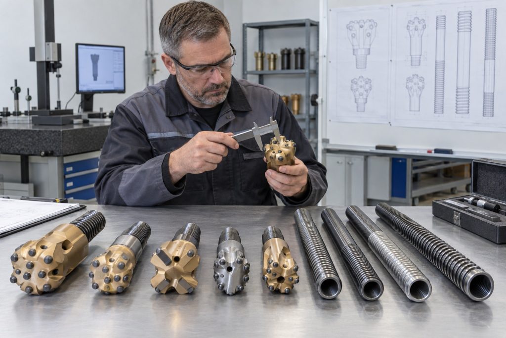
Therefore, match the right thread and bit for a self-drilling rock bolt with the ground and rig energy. Also check bar capacity, coupling compatibility, and the flushing plan. Rope-style threads support rotary-percussive work. Meanwhile, other profiles may suit different load and handling needs. The bit face, carbide layout, diameter, and ports must cut without choking returns. However, a larger bit may increase grout space while also raising torque and spoil volume.
What belongs on your compatibility check?
Treat the drill string as one chain. In practice, review every connection from shank adapter through bit as one approval. Otherwise, a dimensionally correct thread can still fail when rig and bit choices conflict.
- Rig output suits specified bar and bit
- Adapter, bar, coupler, and bit share compatible threads
- Couplers allow full bar-end seating
- Bit diameter supports grout cover required by design
- Flushing ports remain clear under expected cuttings
| Choice | Match against | Site consequence |
|---|---|---|
| Thread profile | Rig, coupler, and design load | Connection and energy transfer |
| Bit face | Formation and cutting behavior | Penetration and steering |
| Port layout | Flush medium and spoil | Return flow and grout path |
Any mismatch can affect both installation and permanent performance. Key Takeaway: As a result, approve a complete compatible string before releasing separate purchase lines.
8. Protect the Bolt With Grout and Coatings
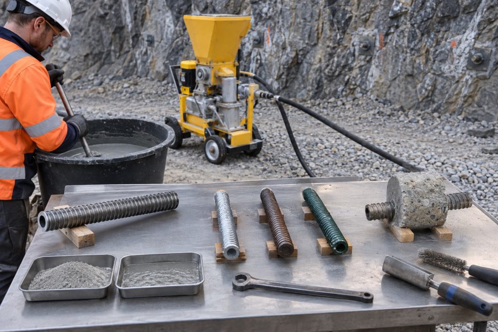
Meanwhile, grout and protective coatings defend a self-drilling rock bolt through different mechanisms. Grout transfers load and fills surrounding voids. At the same time, coatings slow steel exposure. Therefore, your grout plan should define materials, mixing, pumping, return criteria, records, and responses to loss zones. Corrosion measures should also follow design life, groundwater chemistry, stray-current risk, handling damage, and applicable project rules.
Which controls protect installed quality?
Make hidden work traceable. For example, field records should show how grout reached each bore. They should also show how protected steel arrived, moved, and entered service. Otherwise, batch records without bore locations leave weak evidence for later review.
- Verify batch materials and mixing sequence
- Observe pressure trend and return condition
- Record loss, refusal, blockage, or restart
- Inspect coating before installation
- Repair allowed damage under approved procedure
| Protection layer | Main job | Evidence to retain |
|---|---|---|
| Grout body | Bond and void filling | Batch and pumping record |
| Metallic coating | Slower steel exposure | Coating inspection |
| Handling control | Limits surface damage | Delivery and pre-use check |
Together, these records show whether specified protection reached installed work. Key Takeaway: Therefore, protect service life by controlling both bond quality and steel exposure from delivery onward.
9. Choose a Supplier That Owns Compatibility
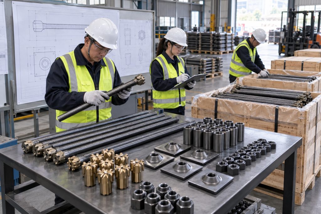
Finally, choose a self-drilling rock bolt supplier that can review your project as one package. Then share your ground profile, drawings, load requirements, equipment, compliance needs, and delivery schedule. In addition, ask for clear material records, product drawings, inspection controls, component matching, packing details, and deviation handling. Remember, a low unit quote cannot recover a stopped rig, rejected shipment, or incompatible coupling underground.
What separates a workable quote from a risky one?
Put evidence beside every promise. For comparison, your request for quotation should show the technical scope, documents, quantity, packing, lead time, and communication duties. It should also name who approves substitutions before production.
- Named bar, bit, coupler, plate, and nut configuration
- Drawings with revision control
- Agreed inspection and document package
- Packaging that protects threads and coatings
- Delivery milestones with exception reporting
- Technical contact for installation questions
| Supplier check | Acceptable evidence | Risk exposed |
|---|---|---|
| Compatibility | Matched component schedule | Mixed threads or undersized parts |
| Quality control | Traceable inspection records | Unverified material or dimensions |
| Delivery | Packing and milestone plan | Damage, shortages, or late arrival |
Therefore, read a quote for omissions before comparing price. Key Takeaway: You reduce procurement risk when one supplier owns compatibility, records, packing, and technical response.
Ready to review your self-drilling rock bolt plan?
Bring one clear brief. Next, use it to review system purpose, component fit, and installation controls. It should also cover ground response, grout, corrosion, and supplier evidence.
- Ground report and bore information
- Drawings, loads, and design life
- Rig, flushing, and grout details
- Required records and delivery schedule
| Project input | Review purpose |
|---|---|
| Ground and loads | Confirm system role and capacity |
| Rig and grout plan | Check installation compatibility |
| Records and schedule | Align quality control with delivery |
These inputs let technical and production teams review one scope. Then, when you contact us today, our team can help shape a matched component schedule and production review. Key Takeaway: Ground support should be specified as one system and delivered with the records needed to trust it.
10. Confirm the Final Technical Questions
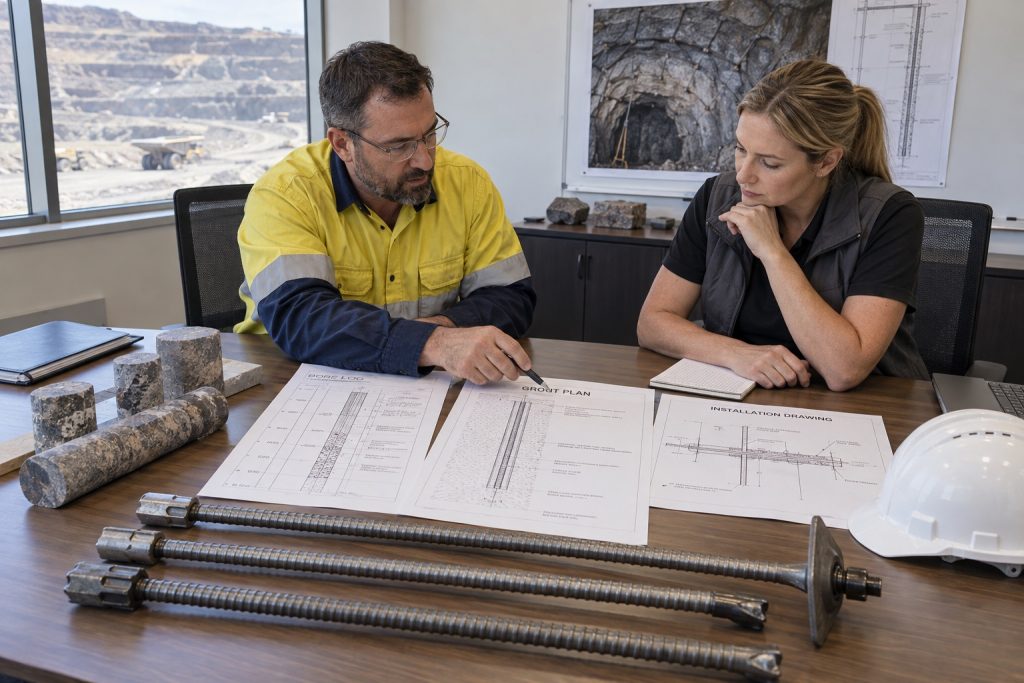
Most importantly, ask whether the self-drilling rock bolt suits your ground, rig, grout plan, loads, design life, and verification method. Together, the following three questions expose common gaps before procurement or site planning. However, bring each answer back through your project engineer. Field conditions and governing rules still control acceptance. Finally, use a short pre-award meeting to expose gaps before material ships.
Can I use a self-drilling rock bolt without casing?
Short answer: yes, in many collapsing formations. The permanent hollow bar supports both drilling and grout delivery. As a result, it often removes a separate temporary casing stage. However, casing may still be needed where equipment, geology, or design calls for it.
- Confirm ground and groundwater assumptions
- Match bit and flushing method with formation
- Run a trial where uncertainty remains
- Follow project design and site controls
This method works best when bore instability drives your choice.
What’s the best bit for fractured rock?
The best choice matches your formation and rig. First, review fracture spacing, hardness, abrasivity, and water. Then match the flushing medium, hole diameter, and available impact energy.
- Share bore logs and core photographs
- Define rig model and drilling method
- Compare bit face and carbide layout
- Review returns during trial installation
For example, a supplier recommendation becomes stronger when backed by site observations. Therefore, trial drilling gives you stronger evidence than a catalog description.
How do I know if grout reached the full bond length?
Records and verification tests provide the answer. First, track mixed and pumped volumes. Then record the pressure trend, visible returns, loss zones, interruptions, and any approved secondary grouting.
- Reconcile grout volume with expected bore geometry
- Record returns at every bore
- Investigate sudden loss or blockage
- Apply specified proof or acceptance tests
These checks give your engineer evidence for acceptance. Therefore, keep the records with bore locations and material traceability. Key Takeaway: You can buy a complete system with confidence after design, installation, and verification questions receive documented answers.