
Rock bolt shear strength describes resistance measured under a stated transverse-loading arrangement, rather than a universal substitute for axial capacity. A buyer can receive two convincing reports with different joints and fixtures. Their peak loads may describe different mechanisms. Identify your proposed steel bolt assembly, then compare how each laboratory actually loaded it.
1. What does rock bolt shear strength represent?
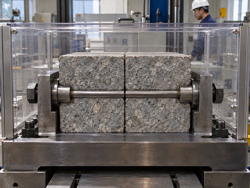
Rock bolt shear strength represents a defined specimen’s response when loading acts across its axis within a particular setup. Underground joint movement can also bend and tension the bar. A reported shear load therefore needs its associated geometry and boundary conditions.
Start with the load path
Look across the joint. Identify which side moves, where the bolt crosses the interface, and how the surrounding material restrains it. Laboratory research comparing full-scale and direct shear methods reports different responses between arrangements. That finding supports reading the setup before using a value, without supplying a universal correction factor.
- Mark the loading direction against the bolt axis.
- Identify each reacting surface and moving block.
- Keep assembly resistance separate from an intrinsic material-property claim.
Shear-result definition
Use bolt-family descriptions for naming context. Ask the laboratory to define its reported result in physical terms.
| Result label | Meaning to establish | Required context |
|---|---|---|
| Applied shear load | Force measured by the apparatus | Load path and interfaces |
| Bolt response | Observed assembly behavior | Bending, tension, and damage |
| Material property | Separately defined test quantity | Specimen and calculation basis |
Key takeaway: read shear results with their fixture drawings. One load number cannot describe every transverse support mechanism.
2. Why are axial ratings insufficient for shear decisions?
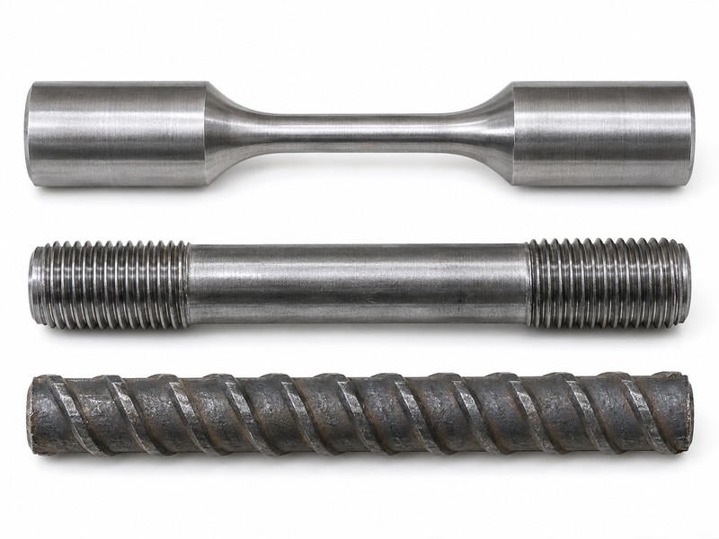
Axial ratings are insufficient because transverse movement changes the stress state and can engage different failure locations. Axial tension primarily pulls along the bar. Joint displacement can introduce local bending, contact forces, and tensile components together.
Recognize the changing deformation mode
Watch the bar near contact. A bolt restrained beside a moving joint may develop curvature where it exits surrounding material. The resisting mechanism then depends on geometry and confinement. A tensile certificate describes its own specimen and loading mode; it cannot establish a general percentage conversion for this situation.
- Identify which axial result a supplier is quoting.
- Request shear-specific evidence where your engineering decision requires it.
- Reject an unexplained conversion between axial load and shear resistance.
Axial versus transverse evidence
Include bearing hardware when it participates in either arrangement. Ask engineers to identify the relevant test mode.
| Loading mode | Main review question | Missing from a simple rating |
|---|---|---|
| Axial tension | How does this specimen resist pulling? | Joint-driven curvature |
| Transverse movement | How does the restrained assembly respond? | Universal axial equivalence |
| Combined loading | How do simultaneous actions interact? | Independent capacities added together |
Key takeaway: match evidence with loading mode. Keep axial certificates in the dossier without relabeling them as shear ratings.
3. How do single and double shear setups differ?
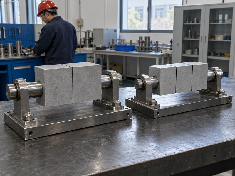
Single and double shear setups differ in the number and arrangement of loaded interfaces acting on the specimen. A double-shear apparatus can load two planes. Reported total force and a normalized per-plane result require distinct labels.
Count physical planes before comparing force
Trace both reactions. Ask the laboratory to show moving and supported pieces in its fixture. Determine whether its summary reports total machine force or another quantity derived from that force. Some published methods normalize double-shear results per plane, but that calculation belongs to the stated arrangement and assumptions.
- Identify the number and spacing of shear planes.
- Preserve the original machine-force result.
- Document any normalization and its justification.
Shear-plane comparison
For hollow-bar configurations, identify section and joint locations relative to each plane. Do not assume a symmetric force distribution without a suitable basis.
| Setup detail | Record | Comparison question |
|---|---|---|
| Plane count | Fixture drawing | One or multiple loaded interfaces? |
| Force label | Total or normalized | Same quantity across reports? |
| Plane spacing | Specimen arrangement | Similar bending opportunity? |
Key takeaway: compare defined force quantities. A hidden division within one report can distort an otherwise careful numerical comparison.
4. How does joint opening change the response?
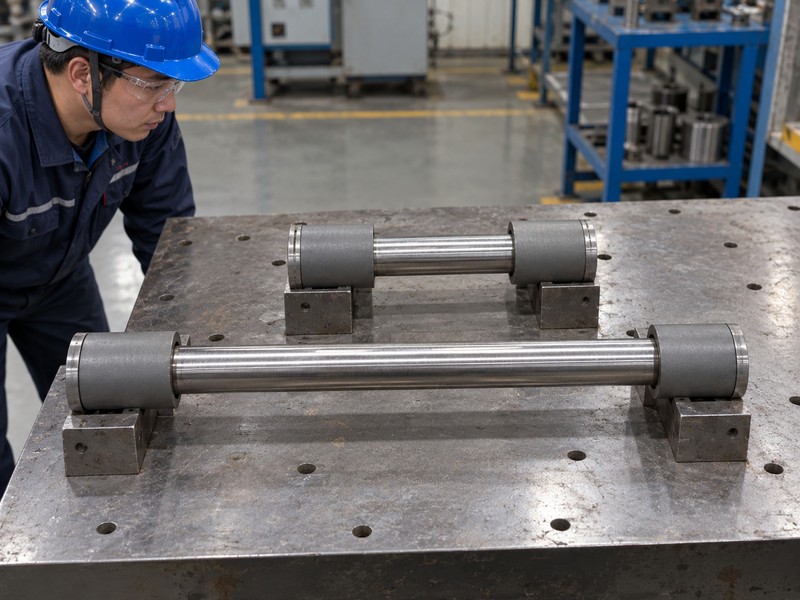
Joint opening changes the unsupported region available for bolt bending and interaction with surrounding material. A tightly restrained interface differs from a gap that permits curvature. Joint geometry belongs beside every displacement and load result.
Describe the gap as part of the specimen
Measure the interface you tested. Record initial opening, surface arrangement, and any permitted separation during movement. Ask how the bolt contacts nearby edges and whether those edges damage or restrain it. A sharp fixture contact may promote a different local failure from a deformable host material.
- Record initial joint geometry and bolt crossing orientation.
- Document changes in opening during the test where observed.
- Identify contact edges and their relationship with the specimen.
Joint-geometry record
Include relevant accessory interfaces when they affect restraint. Ask the reviewer which geometric differences prevent direct comparison.
| Joint feature | Evidence | Possible mechanism |
|---|---|---|
| Initial gap | Drawing and photograph | Available bending span |
| Contact edge | Fixture detail | Local contact or cutting action |
| Separation during movement | Observations or measurements | Changing axial contribution |
Key takeaway: joint geometry shapes deformation. A shear result without that geometry leaves its governing mechanism uncertain.
5. Why does surrounding material need identification?
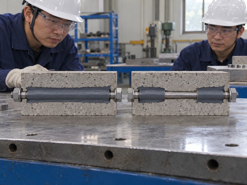
Surrounding material needs identification because its stiffness, crushing, and contact behavior affect bolt restraint and load transfer. A steel fixture and a simulated rock block can impose different conditions. Those differences may alter both load and displacement.
Distinguish bolt movement from host damage
Inspect beside the bar. Local crushing can allow curvature and change how force reaches the steel. Grout or resin can also deform or separate at an interface. Ask the report to describe observed host damage rather than attributing every change in the curve to the bolt material.
- Record host material, confinement, and preparation details.
- Identify encapsulation and available curing records where relevant.
- Photograph crushing, cracking, or interface movement after testing.
Host-condition comparison
Your tunnel support context helps frame relevance. It does not establish that a laboratory host reproduces every site condition.
| Surrounding feature | Record | Interpretation effect |
|---|---|---|
| Host material | Stated properties and preparation | Restraint and local crushing |
| Confinement | Fixture arrangement | Permitted deformation |
| Encapsulation | Material and geometry | Interface load transfer |
Key takeaway: assess host behavior with steel behavior. Different surrounding materials can produce different assembly responses without changing the bar grade.
6. How do preload and crossing angle enter interpretation?
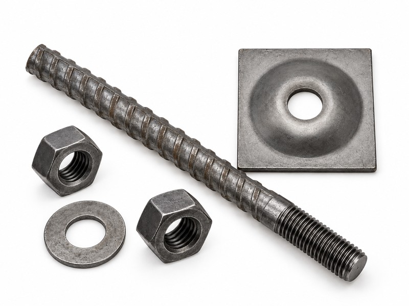
Preload and crossing angle enter interpretation by changing the initial force state and the relationship between joint movement and bolt deformation. Their effects depend on the actual arrangement. A report should state whether these parameters were controlled, measured, or absent.
Preserve the starting configuration
Draw the initial force state. A bar crossing an interface obliquely does not follow the same geometry as a perpendicular bar. An applied axial preload also changes its starting condition. Ask engineers to evaluate these combined effects rather than adding separate axial and shear capacities arithmetically.
- Record bolt angle relative to the joint and movement direction.
- Identify any applied preload and its measurement method.
- Preserve changes in restraint during loading.
Initial-condition matrix
A friction bolt specimen also requires its actual contact and installation condition. Avoid importing assumptions from another support mechanism.
| Initial condition | Record | Review concern |
|---|---|---|
| Crossing angle | Defined geometric reference | Different axial and transverse components |
| Preload | Measured or specified basis | Different starting force state |
| Head restraint | Actual test arrangement | Changed permitted movement |
Key takeaway: preserve initial conditions. Similar peak loads may arise from different combinations of tension, bending, and transverse resistance.
7. Which displacement does a shear report describe?
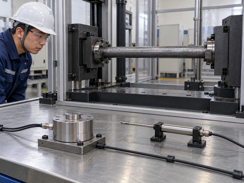
A shear report may describe machine movement, relative joint displacement, or another defined measurement. These quantities are not automatically interchangeable. Fixture compliance and local deformation can separate machine travel from movement at the loaded interface.
Ask for measurement reference points
Locate both ends of the measurement. Request a drawing showing sensor references and movement direction. Read load–displacement histories alongside photographs and reported events. Where the apparatus measures several displacements, keep their labels distinct in summary tables. A maximum needs a defined channel and test stage.
- Identify machine, joint, and local specimen measurements separately.
- Record processing and zeroing arrangements.
- Preserve loading-rate information used by the laboratory.
Displacement-definition record
Keep pull-test displacement separately labeled if included in a broader dossier. It measures another loading arrangement.
| Measurement | Reference | Comparison concern |
|---|---|---|
| Machine travel | Machine components | Includes apparatus deformation |
| Joint displacement | Opposing host regions | Defined interface movement |
| Local deformation | Specimen or nearby references | Different physical quantity |
Key takeaway: compare matching displacements. A long machine stroke does not by itself establish ductile steel behavior at the joint.
8. How should failure location be documented?
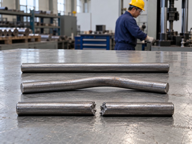
Document failure location against the original geometry, together with visible host and accessory damage. Rupture at a contact edge differs from interface slip or a grip failure. A laboratory endpoint should not obscure that distinction.
Read the failed assembly
Keep the pieces identifiable. Photographs should retain orientation and show where damage occurred relative to each loaded plane. Ask whether fracture, excessive movement, apparatus limits, or another criterion ended the test. Report unusual observations and invalid runs instead of silently treating every number as a comparable capacity.
- Mark rupture, bending, slip, and damaged host regions.
- Retain specimen identity in post-test photographs.
- Record the laboratory’s validity and stopping criteria.
Failure-observation table
Request technical interpretation where several mechanisms occur together. Let the reviewer state which result can support the proposed engineering decision.
| Observation | Location detail | Interpretation question |
|---|---|---|
| Steel rupture | Relative to contact planes | Localized or distributed mechanism? |
| Host damage | Adjacent to bolt | Changed restraint during loading? |
| Grip or fixture issue | Apparatus interface | Valid specimen result? |
Key takeaway: failure photographs belong with result tables. They help distinguish specimen behavior from limitations of the apparatus.
9. When can two shear reports be compared?
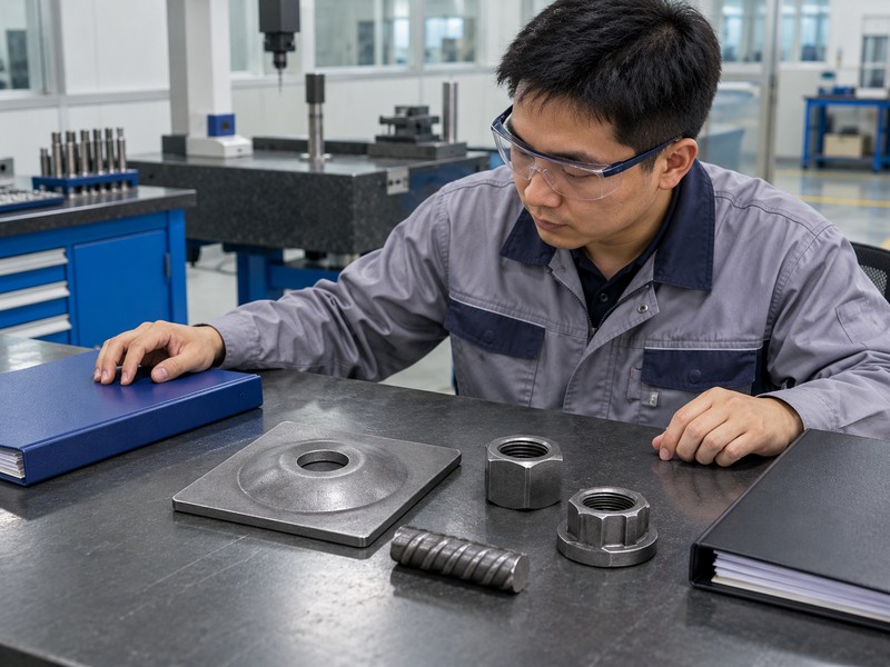
Two shear reports can support a direct comparison when relevant specimen, loading, restraint, and measurement conditions align sufficiently for the stated decision. A qualified reviewer should identify remaining differences. A shared bolt diameter alone provides too little context.
Build a mechanism-based comparison
Compare causes of resistance. Check whether both arrangements permit similar bending, contact, and host deformation. Confirm that reported forces and displacements use matching definitions. Where differences remain, request clarification or a matched test rather than applying an invented correction factor.
- Match hardware identity and specimen condition.
- Compare joint, host, and loading arrangements.
- Record evidence gaps before numerical ranking.
Comparability status
Use clear statuses in procurement summaries so unresolved method differences remain visible. Ask reviewers to explain qualifications beside any proposed comparison.
| Review status | Evidence condition | Buyer response |
|---|---|---|
| Comparable for stated purpose | Relevant conditions aligned | Qualified comparison |
| Partly comparable | Differences understood | State limitations |
| Unresolved | Missing or incompatible details | Request further evidence |
Key takeaway: qualify the comparison purpose. A test can be useful without supporting a universal ranking of shear performance.
10. What should a shear-test enquiry include?
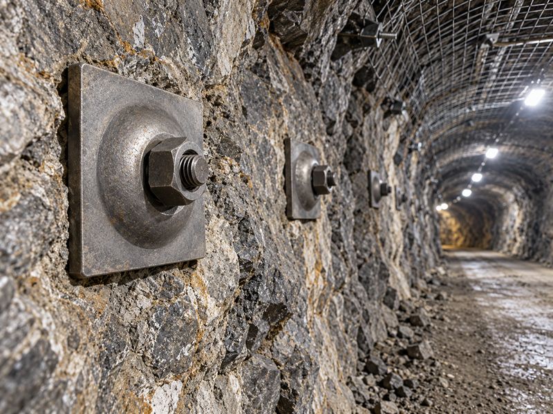
A shear-test enquiry should define the proposed assembly, loading question, joint geometry, boundaries, measurement needs, and reporting expectations. Rock bolt shear strength requires those conditions before a useful test program can be proposed. Ask the laboratory and project engineer to agree its scope.
Specify the mechanism you need investigated
Send more than a target load. Provide drawings and describe the relevant joint movement without inventing a laboratory method yourself. Request apparatus diagrams, individual results, force and displacement definitions, and post-test photographs. Keep axial ratings separately identified so every evidence item retains its original meaning.
- Request a complete specimen and boundary-condition schedule.
- Ask how total and normalized shear forces will be labeled.
- Require documented failure locations and test endpoints.
Obtain assembly-specific evidence
| Closure check | Action to retain |
|---|---|
| 1 | Request a complete specimen and boundary-condition schedule. |
| 2 | Ask how total and normalized shear forces will be labeled. |
| 3 | Require documented failure locations and test endpoints. |
For a steel support hardware discussion, contact us with drawings and the proposed test scope. Request evidence for that configuration before assigning a shear rating or accepting a conversion from tensile data.
Q1: Can I calculate shear capacity from tensile strength alone? No general conversion is justified here. Geometry, restraint, combined loading, and the required design model need separate review.
Q2: How do I know if a value is per shear plane? Read the force definition and calculation. Ask whether the report presents total machine force or a normalized result.
Q3: What’s the best displacement value to compare? Compare matching physical measurements. Machine travel and relative joint movement can include different deformation components.
Q4: Can a stronger host change measured shear response? Yes, restraint and local damage can change. Their effect requires interpretation for the actual specimen and setup.
Q5: Should I reject a test that ended without rupture? Not automatically. Review its stopping criterion and determine which conclusions that endpoint can support.