
Rock bolt fatigue testing examines response and damage under repeated cyclic loading within a defined specimen and procedure. A report saying survived many cycles still leaves open what loads, frequency, and endpoint were used. Compare that history before comparing durability. Identify the proposed steel bolt configuration separately from any laboratory specimen or service-life claim.
1. What question should rock bolt fatigue testing answer?
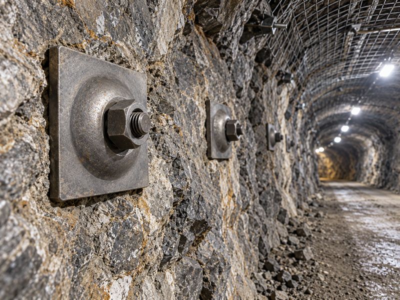
Rock bolt fatigue testing should answer how a defined specimen responds to a specified repeated loading history. Its purpose may concern steel damage, interface degradation, or another identified mechanism. Those questions need different specimen configurations and observations.
Define the damage mechanism of interest
Choose the tested object deliberately. A smooth steel specimen isolates a different problem from a bolt embedded in a simulated host. An embedded assembly can develop damage in surrounding material or interfaces. Published cyclic-bolt research examines those system effects, so its cycle counts must retain their specimen context.
- State whether the enquiry concerns material or an assembly.
- Identify which damage mechanism the program should observe.
- Specify the engineering decision requiring cyclic evidence.
Test-purpose register
Use bolt-family terminology for initial identification. Ask your technical reviewer to define the actual tested object.
| Test purpose | Specimen context | Evidence needed |
|---|---|---|
| Steel fatigue | Defined material geometry | Load history and fracture |
| Interface damage | Embedded assembly | Relative movement and bond observations |
| System response | Identified complete arrangement | Participating failure mechanisms |
Key takeaway: define the damage question before comparing life. Different specimens can fail in different materials under the same nominal label.
2. Why do maximum and minimum loads both matter?
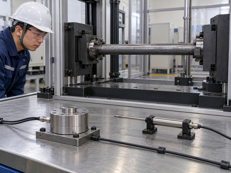
Maximum and minimum loads both matter because together they define mean load and cyclic amplitude. Two tests can share a maximum while experiencing different fluctuations. A cycle count without both limits leaves loading severity incompletely described.
Separate mean from range and amplitude
Keep both endpoints visible. Mean load sits halfway between the maximum and minimum. Load range is their difference, while amplitude is half that range. A reported ratio also needs its definition, commonly minimum divided by maximum. Preserve sign conventions and avoid assuming every cyclic test reverses loading direction.
- Record maximum and minimum values with units.
- Identify whether results use force or stress.
- Preserve definitions for range, amplitude, mean, and ratio.
Cyclic-load definitions
Include relevant bearing hardware in assembly identity where it participates. Ask reviewers to compare complete load histories.
| Parameter | Definition | Missing-information risk |
|---|---|---|
| Mean | Midpoint of load limits | Different starting load state |
| Range | Maximum minus minimum | Different fluctuation size |
| Amplitude | Half the range | Range mistaken for amplitude |
Key takeaway: require both load limits. A maximum alone cannot establish whether two fatigue programs applied comparable cyclic demand.
3. How do force and displacement control differ?
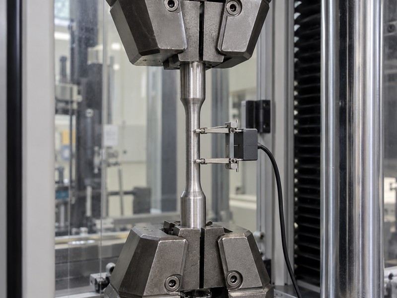
Force-controlled tests regulate a prescribed force history, while displacement-controlled tests regulate a prescribed movement history. The other response can evolve as a specimen changes. Their cycle counts therefore need different interpretation within the test’s actual control strategy.
Identify what the machine maintained
Follow the controlled channel. If an assembly becomes more compliant, maintaining a force history may require changing movement. Maintaining a movement history may instead produce a changed force response. Ask the laboratory which limits, feedback arrangements, and interruptions applied throughout the program.
- Record the controlled quantity and loading waveform.
- Preserve measured response histories rather than command settings alone.
- Identify changes in control mode during testing.
Control-mode review
For hollow-bar assemblies, confirm the actual specimen and joints included. Control-mode terminology cannot establish product equivalence.
| Control mode | Maintained input | Response to inspect |
|---|---|---|
| Force | Specified force history | Evolving displacement |
| Displacement | Specified movement history | Evolving force |
| Changed or mixed | Defined sequence | Transition and accumulated history |
Key takeaway: compare measured histories under known control modes. A command value alone does not show what the specimen experienced.
4. Why must frequency and waveform be reported?
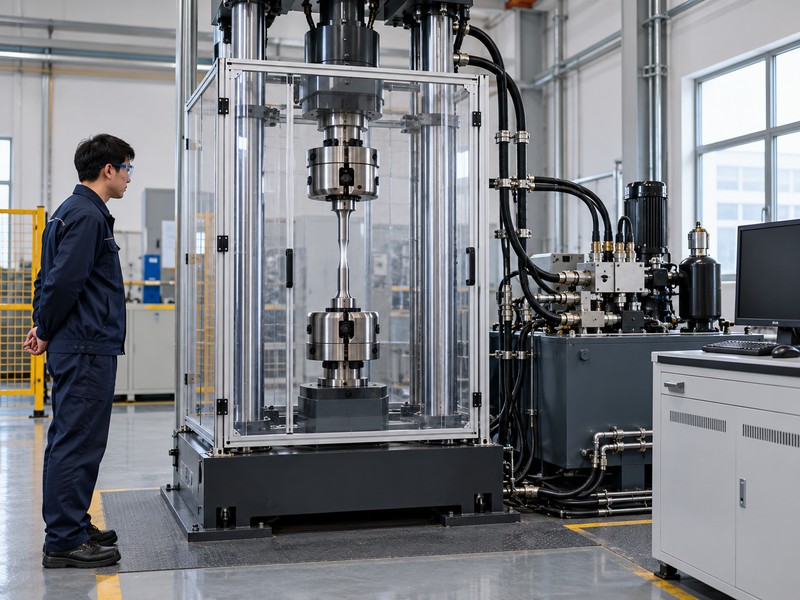
Frequency and waveform describe how loading changes with time, beyond its maximum and minimum values. A rounded periodic cycle differs from a sequence with holds or abrupt changes. The effect of those differences depends on material and assembly behavior.
Preserve time as a test parameter
Describe the whole cycle. Frequency specifies cycles per unit time, while waveform defines the path between load limits. Holds, interruptions, and restarts add further history. Published bolt-system research investigates frequency and amplitude effects, but its findings do not establish one universal rule for every support configuration.
- Record frequency and waveform throughout the test.
- Document holds, interruptions, and changed settings.
- Ask about temperature observations where relevant to the method.
Time-history schedule
Include accessory interfaces when they form part of cyclic movement. Ask the laboratory which time-related effects its procedure controls or observes.
| Timing parameter | Record | Comparison concern |
|---|---|---|
| Frequency | Actual test setting or history | Different loading rate |
| Waveform | Shape and holds | Different time near limits |
| Interruption | Duration and specimen condition | Changed loading history |
Key takeaway: compare time histories as well as limits. Equal cycle counts do not establish equal experiments.
5. How do geometry and surface condition affect scope?
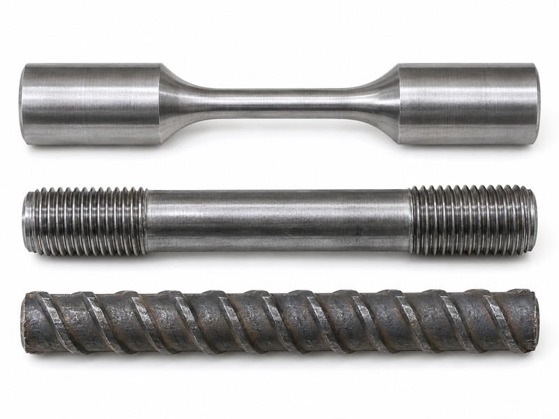
Geometry and surface condition affect the scope of a fatigue result because local stress and damage initiation can depend on specimen features. A smooth specimen differs from a threaded or finished component. Preserve those differences instead of transferring one life result automatically.
Identify features present during cycling
Look at the local detail. Ask whether threads, ribs, joints, coatings, and original surfaces remain in the specimen. Record preparation and any visible pre-existing damage. Changes in geometry or surface condition need a justified interpretation before a material result supports a finished-product claim.
- Identify specimen dimensions and retained product features.
- Preserve source and preparation records.
- Document any deliberately introduced notch or altered surface.
Specimen-scope review
Your tunnel support configuration establishes the proposed application. Compare its relevant features with those actually tested.
| Specimen feature | Evidence | Scope question |
|---|---|---|
| Geometry | Drawing and preparation | Which local features were loaded? |
| Surface | Supplied and tested condition | Same potential initiation sites? |
| Component interfaces | Complete configuration | Same participating parts? |
Key takeaway: preserve the features that were tested. A material fatigue result does not automatically establish finished assembly durability.
6. How can host and interface damage change a cycle count?
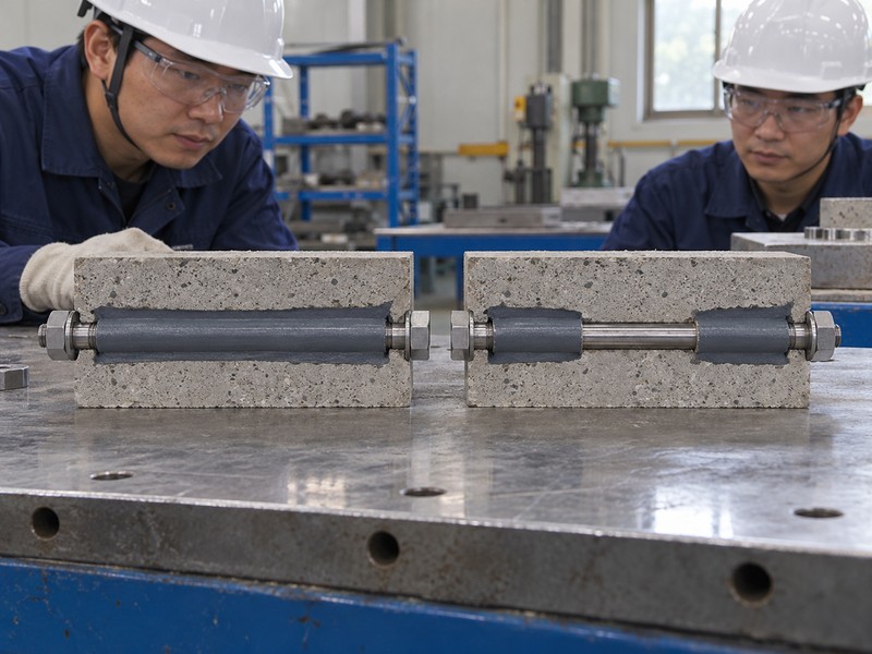
Host and interface damage can change a cycle count by altering restraint and load transfer before steel fracture occurs. An embedded bolt test may end through surrounding-material cracking or debonding. Its result should identify the mechanism that governed the endpoint.
Distinguish system damage from steel fatigue
Inspect outside the bar. Movement can accumulate at interfaces even when the visible steel remains intact. Changing displacement or stiffness may reflect several participating materials. Ask the laboratory how it distinguishes bolt deformation, interface movement, and host damage within its measurement arrangement.
- Record host material and confinement.
- Identify encapsulation geometry and preparation.
- Preserve observed damage locations and relative movement.
Embedded-specimen interpretation
A friction bolt assembly uses a different load-transfer mechanism from a bonded bar. Keep its cyclic evidence within its tested configuration.
| Damage location | Observation | Interpretation limit |
|---|---|---|
| Steel | Crack or fracture | Specimen-specific fatigue behavior |
| Interface | Relative movement or debonding | Changed load transfer |
| Host material | Cracking or splitting | System endpoint outside steel |
Key takeaway: name the damaged material. A cycle count for host failure cannot be relabeled as the steel’s fatigue life.
7. What can stiffness and acoustic observations tell you?
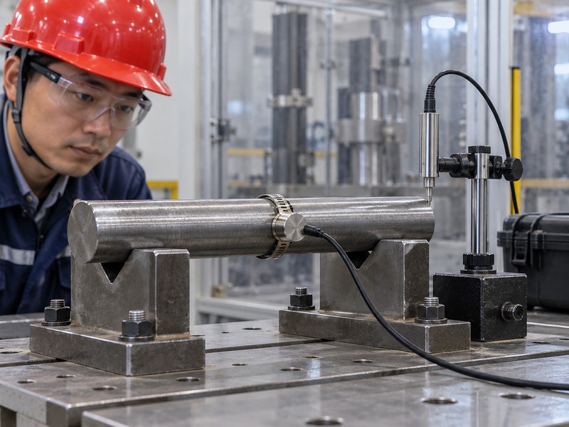
Stiffness and acoustic observations can help track changes during a test when their measurement and interpretation methods are defined. They do not independently establish remaining service life. A damage indicator requires a validated relationship for its stated purpose.
Separate indicators from physical conclusions
Follow the measurement definition. A stiffness measure needs stated force and displacement references. Acoustic-emission observations need acquisition settings and an interpretation basis. Published bolt experiments use acoustic monitoring to study damage evolution, but their indicators cannot be transferred directly to another system without validation.
- Request definitions for reported stiffness or damage variables.
- Preserve sensor locations and processing settings.
- Correlate indicators with documented physical observations where available.
Damage-indicator review
Keep static pull-test evidence separately identified when included. It answers another loading-history question.
| Indicator | Basis required | Unsupported conclusion |
|---|---|---|
| Stiffness change | Defined measured relationship | Specific crack location automatically known |
| Acoustic activity | Acquisition and interpretation | Universal remaining-life estimate |
| Damage variable | Stated model and validation | Direct mine service-life prediction |
Key takeaway: request the indicator’s meaning. Keep model-derived damage separate from directly observed fracture or movement.
8. How should runouts and stopping criteria be reported?
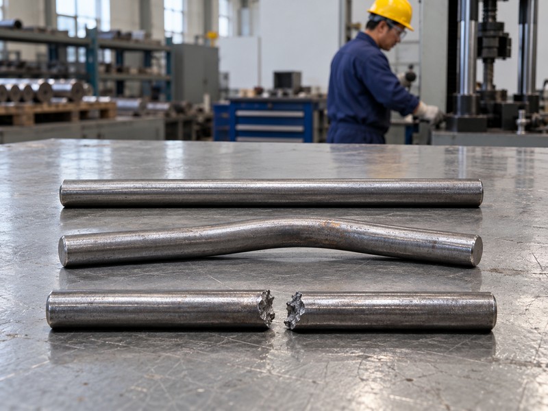
A runout means a specimen reached a stated test limit without meeting the defined failure criterion. It does not establish infinite life. Reports should separate runouts, observed failures, interrupted tests, and equipment-related stops.
Keep the endpoint with the cycle count
Ask why cycling stopped. A specimen may remain intact when a planned limit is reached. Another test may stop after a displacement threshold or a control problem. These outcomes provide different evidence. Preserve the actual endpoint and specimen condition rather than placing every final count in a column labeled fatigue life.
- Identify the planned limit and failure criterion.
- Record actual stopping reason for each specimen.
- Preserve interruptions and post-test observations.
Endpoint categories
Ask the qualified reviewer how each category enters a comparison or statistical analysis. Do not discard runouts or treat them as observed failures without a stated method.
| Endpoint | Meaning | Reporting requirement |
|---|---|---|
| Observed failure | Defined criterion reached | Mechanism and cycle count |
| Runout | Planned limit reached | Criterion not reached |
| Other stop | Test interrupted or constrained | Reason and specimen condition |
Key takeaway: compare outcomes with their endpoints. A final count has little meaning without knowing why the machine stopped.
9. When can laboratory fatigue results support service decisions?
Laboratory results can support service decisions when a qualified assessment connects test conditions with relevant service conditions and states its limitations. Laboratory cycles do not convert directly into calendar life. Variable loading, environment, and actual assembly conditions need separate consideration.
Require a stated transfer basis
Keep the service assumption explicit. Ask which real loading history the laboratory program represents and which conditions remain outside scope. A fitted life curve needs its supporting data, specimen population, and statistical method. One successful specimen at one setting cannot establish a complete fatigue curve or universal endurance limit.
- Identify matched and unmatched service conditions.
- Preserve individual outcomes and relevant scatter.
- Require qualified interpretation before assigning design or life claims.
Service-transfer review
Use the review to identify evidence gaps rather than inventing an acceleration factor. Ask for additional work only where it supports a defined engineering decision.
| Transfer question | Evidence needed | If absent |
|---|---|---|
| Loading relevance | Documented comparison | Qualify application |
| Environmental relevance | Stated conditions | Avoid unsupported life claim |
| Statistical basis | Individual data and method | Limit population conclusions |
Key takeaway: retain test-to-service assumptions. A cycle count alone cannot establish years of reliable support.
10. What should your cyclic-test enquiry include?
Your enquiry should specify the tested object, load-history definitions, control mode, observations, endpoints, and reporting deliverables. Rock bolt fatigue testing requires that context before meaningful evidence can be generated. Ask qualified specialists to propose a program appropriate for your decision.
Send a complete loading question
Specify the comparison you need. Provide drawings, material identity, assembly condition, and available service context. Request actual measured histories, individual specimen outcomes, and damage observations. Keep continuous cyclic testing separate from discrete drop-impact energy comparisons and field anchorage checks.
- Ask how maximum, minimum, amplitude, mean, and ratio will be defined.
- Request frequency, waveform, interruptions, and control-mode records.
- Require explicit runout, failure, and other stopping categories.
Request evidence within its scope
| Closure check | Action to retain |
|---|---|
| 1 | Ask how maximum, minimum, amplitude, mean, and ratio will be defined. |
| 2 | Request frequency, waveform, interruptions, and control-mode records. |
| 3 | Require explicit runout, failure, and other stopping categories. |
For a steel support hardware discussion, contact us with drawings and your proposed cyclic-test question. Request product-specific evidence before making fatigue, endurance, or service-life claims about an offered configuration.
Q1: Can I compare tests with the same maximum load? Only after checking minimum load and the remaining conditions. Equal maxima can conceal different cyclic amplitudes and means.
Q2: How do I know whether a cycle count represents steel failure? Read the endpoint and damage location. Embedded systems can stop because of host or interface damage.
Q3: What’s the best interpretation of a runout? Treat it as survival to a stated limit under stated conditions. It does not establish infinite life.
Q4: Can acoustic emissions predict remaining support life? Only within a suitably validated model. A published experimental indicator cannot automatically predict another installation’s remaining life.
Q5: Should fatigue cycles be converted into years? Only through a justified service assessment. Loading history, environment, specimen representation, and uncertainty require qualified treatment.