
Instrumented rock bolts measure strain along installed reinforcement so engineers can examine loading changes and their locations. A mine may receive tidy trend plots yet lack sensor positions, reference readings, or event times. You need a monitoring plan before ordering instruments. Start with identified steel bolt hardware, then specify sensing coverage and reporting responsibilities separately.
1. What should instrumented rock bolts help you decide?
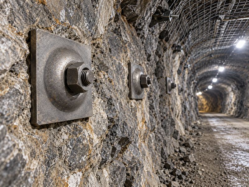
Instrumented rock bolts should answer a defined support question, such as where strain changes occur during a scheduled mining sequence. A drawing full of sensor symbols cannot establish that question. Write down which engineering decision each location supports before choosing channel counts.
Define the decision before the sensor
Start with an observable change. You might need strain distribution near a mapped discontinuity or changes following nearby excavation. Those questions require different locations and reporting schedules. Record expected events without predicting their measured effects. Existing bolt type information can help name hardware families when assembling this register.
- Name the decision owner and expected review date.
- Connect every monitored location with a specific geological or operational question.
- State which observations would require engineering review.
Monitoring decision register
Keep acceptance criteria separate from exploratory measurements. Ask your rock engineer to approve objectives and response responsibilities before procurement starts.
| Planning item | Record required | Buyer check |
|---|---|---|
| Support question | Named loading concern | Specific enough for a decision |
| Location | Survey reference and orientation | Recoverable underground |
| Response owner | Role and contact route | Available during monitoring |
Key takeaway: every instrument needs a stated purpose. Remove channels that cannot inform an approved decision.
2. Which measurements belong in the same report?
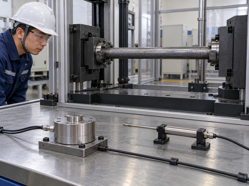
A monitoring report should distinguish measured strain, calculated axial force, and inferred bending or shear behavior. These outputs depend on different assumptions. A number labeled load needs an explanation of its calculation and applicable range.
Under axial stretching, opposing faces can show a common strain component. Bending adds different strains across those faces. Separating those effects requires sensor orientation and a suitable reconstruction model, rather than treating one surface reading as axial strain.
Identify measured and derived quantities
Keep the calculation visible. A sensor measures its own response within an installed assembly. Converting strain into force requires relevant section properties and a suitable material relationship. Opposed measurements can help separate axial and bending contributions under an appropriate model. A head-mounted cell measures a different location from sensors distributed along a bar.
- Label raw readings separately from engineering calculations.
- Record section properties and calibration references behind each conversion.
- Identify plate or head measurements without implying full-length coverage.
Measurement classification
Include bearing plate identity when head reactions form part of your monitoring package. Ask for a sample export showing units and calculation labels.
| Output | Direct observation | Qualification needed |
|---|---|---|
| Sensor response | Instrument signal | Calibration and channel health |
| Strain | Calibrated deformation response | Reference state and temperature |
| Calculated force | Model-derived result | Geometry and material assumptions |
Key takeaway: request a report legend before buying hardware. Readers should recognize calculated quantities immediately.
3. How much of each bolt will you observe?
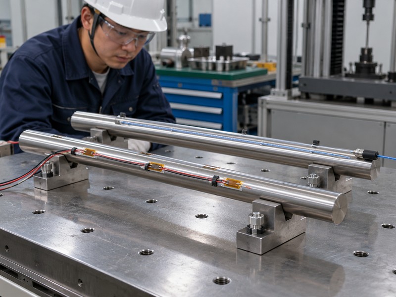
You observe only locations and directions covered by a functioning sensing arrangement. Instrumented rock bolts with local gauges can leave gaps between measurement points. Distributed sensing also requires a defined usable length and spatial interpretation.
A narrow opening can concentrate deformation over a short interval. A local gauge outside that interval may miss it, while a longer gauge can average its peak. Coverage and averaging length therefore answer different questions.
Map coverage rather than channel totals
Draw the blind spots. A high channel count says little without positions and orientation. Published optical-fiber development work identifies spatial coverage and loading direction as practical interpretation problems. Treat that finding as a reason for a coverage drawing. Do not transfer any research prototype’s resolution into a supplier specification without verification.
- Mark sensing positions from a physical reference end.
- Show usable, unsensed, and protected connector lengths.
- Describe directional sensitivity and how orientation will be recorded.
Coverage drawing review
For hollow-bar systems, request drawings specific to that geometry. Avoid assuming an instrumentation layout for solid bars fits every section.
| Coverage detail | Drawing evidence | Interpretation risk |
|---|---|---|
| Axial position | Distance from reference | Peak falls between sensors |
| Orientation | Direction reference | Bending interpretation uncertain |
| Usable length | Active sensing interval | Unobserved end mistaken for quiet ground |
Key takeaway: approve a coverage drawing alongside channel counts. Empty intervals should remain visible in subsequent reports.
4. What calibration records should accompany delivery?
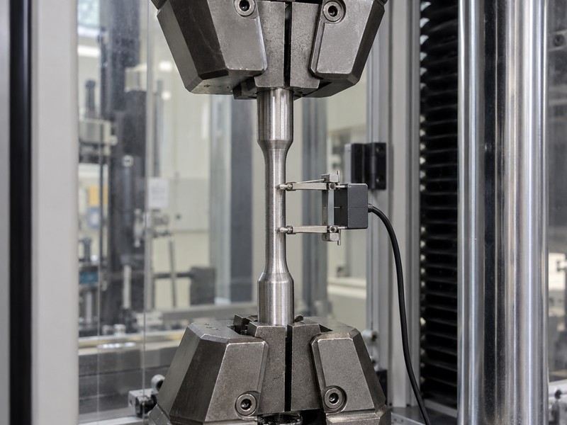
Calibration records should connect each delivered instrument with its sensing channels, reference method, and relevant measurement range. A generic certificate cannot establish individual channel behavior. Procurement should request usable files and identification rather than a certificate title alone.
Check the entire measurement chain
Follow one channel end to end. Match its physical position with connector mapping, acquisition configuration, and exported column name. Ask how calibration applies after installation and which operations require another check. Where bending or temperature correction forms part of processing, request its documented method and limitations.
- Match serial numbers across hardware and calibration files.
- Record acquisition equipment and processing configuration versions.
- Identify checks possible underground without changing bolt loading.
Calibration delivery checklist
Include connector and protective accessory details in this review. Ask the supplier to demonstrate one complete channel trace before dispatch.
| Record | Required connection | Review action |
|---|---|---|
| Instrument identity | Serial and drawing | Match delivered assembly |
| Channel calibration | Position and units | Trace exported columns |
| Processing version | Calculation settings | Preserve reproducible results |
Key takeaway: calibration evidence should be traceable through the exported report. Resolve mismatched channel names before field deployment.
5. When should reference readings be taken?
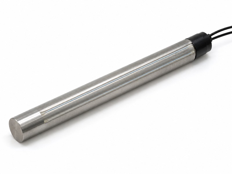
Reference readings should represent a documented installation and operating state chosen by your monitoring engineer. Their timing changes what later strain increments mean. A reference taken after an event cannot recover deformation that occurred beforehand.
Preserve the installation timeline
Give zero a timestamp. Record checks before installation, installation completion, reference acquisition, and subsequent operational events where available. Explain whether plots show absolute calibrated values or changes from a selected baseline. Never relabel a late baseline as an unloaded condition merely because its plotted value starts at zero.
- Record installation state and available curing information without inventing required waiting periods.
- Document reasons for resetting a baseline.
- Retain previous references when processing settings change.
Reference-state record
Your tunnel support context helps describe location, while project records establish actual installation conditions. Approve reference timing within the monitoring plan.
| Reference field | Record | Potential misunderstanding |
|---|---|---|
| Timestamp | Acquisition time | Event occurred before baseline |
| Installation state | Documented condition | Zero assumed to mean unloaded |
| Reset history | Reason and authorization | Discontinuous trends appear continuous |
Key takeaway: a baseline describes a state. Keep its history whenever interpreting changes across construction stages.
6. How do you separate signal changes from faults?

You separate likely loading changes from instrument faults through channel checks, corroborating observations, and documented review. A missing signal does not prove an unloaded bolt. A sudden jump also needs investigation before being interpreted as ground movement.
Temperature can change optical response without an equivalent change in mechanical loading. A compensation arrangement needs its own reference and processing history. Treat temperature correction as a documented calculation rather than an invisible software default.
Put data quality beside engineering results
Inspect the connection first. Optical-fiber research reports practical difficulties involving connectors, temperature effects, and damaged sensing paths. Your supplier should explain how its particular system identifies those conditions. Keep data-quality flags beside plotted results rather than hiding them in a separate maintenance spreadsheet.
- Track signal availability and diagnostic messages for each channel.
- Record temperature measurements or documented compensation arrangements.
- Compare adjacent channels without assuming neighboring bolts carry identical loading.
Fault-review categories
If a monitoring location uses friction bolt hardware, document that configuration explicitly. Do not import calibration or interpretation assumptions from another bolt family.
| Observation | Initial question | Report treatment |
|---|---|---|
| Missing channel | Cable or sensor fault? | Mark unavailable |
| Abrupt step | Event or connection change? | Flag pending review |
| Broad drift | Temperature or reference change? | Retain correction history |
Key takeaway: uncertain readings need a visible status. Preserve raw data before repairing or reprocessing channels.
7. Which site events belong beside strain histories?
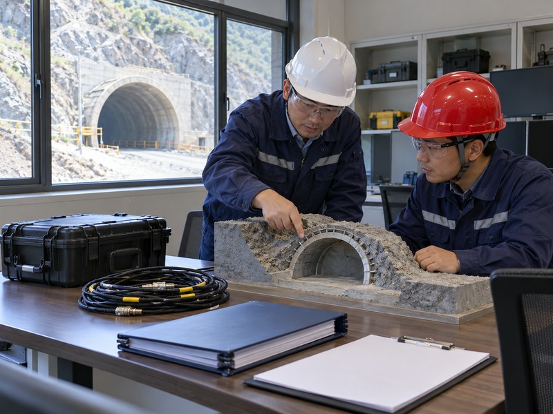
Include events that could affect support response, measurement access, or acquisition continuity. Matching timestamps helps engineers examine relationships without claiming that every nearby activity caused a change. Event logging should use one agreed time convention.
Build a common event register
Put operations on the same clock. An unexplained offset between logger time and shift records can reverse an apparent sequence. Document time zone, clock corrections, and acquisition gaps. Log relevant geological observations separately from interpretations so later reviewers can reconsider competing explanations.
- Record excavation stages and mapped changes near monitored areas.
- Identify equipment maintenance, connector work, and power interruptions.
- Add inspection observations with location and observer role.
Event correlation controls
Choose a coordinator who can obtain mine records without editing original entries. Ask engineers to distinguish observed timing from proposed causal explanations.
| Event field | Useful detail | Review purpose |
|---|---|---|
| Operational event | Location and recorded time | Compare relevant activity |
| Instrument event | Channel and maintenance task | Explain measurement discontinuity |
| Geological observation | Mapping reference | Check loading interpretation |
Key takeaway: synchronize records before comparing trends. Preserve uncertainty where an event time was estimated from shift notes.
8. How should reports handle changing load profiles?

Reports should preserve position, time, channel health, and processing assumptions for each changing profile. Instrumented rock bolts provide observations within a monitoring model. Converting a profile into a support decision requires project engineering review.
Keep spatial and time views together
Read along the bar. A single maximum can conceal movement of a strained zone between surveys. Request position-based profiles alongside selected channel histories. Show missing coverage rather than connecting curves across unavailable data. Where interpretation changes, retain the earlier report and explain the revision.
- Include a position reference consistent with installation drawings.
- Separate measured points from interpolation or derived profiles.
- Provide downloadable data alongside readable plots.
Report content review
Keep pull-out test records separately identified if supplied for another purpose. They do not replace service-load histories.
| Report view | Question answered | Required qualification |
|---|---|---|
| Spatial profile | Where did response change? | Coverage and orientation |
| Channel history | When did response change? | Baseline and time convention |
| Summary alert | Who must review? | Approved trigger and owner |
Key takeaway: retain spatial information. An isolated peak value rarely provides enough context for an engineering response.
9. Who reviews alerts and missing data?

A named engineering role should review alerts, while an assigned instrumentation role handles data availability and equipment faults. Their responsibilities can overlap, but neither should remain implicit. The monitoring plan needs an escalation route for unanswered notifications.
Agree responses before the pilot starts
Assign the next action. Set project-specific review triggers with qualified engineers rather than importing universal strain thresholds. Include a response for unavailable data during relevant operations. Equipment health notifications and engineering alerts may require different recipients and urgency. Record acknowledgment and disposition without making the monitoring system your sole ground-control decision mechanism.
- Name primary and backup reviewers for each alert category.
- Define who can change thresholds or processing settings.
- Document what information accompanies an escalation.
Responsibility matrix
Test the notification route during commissioning. Confirm that people can recognize a practice message and locate its supporting record.
| Condition | Responsible role | Required record |
|---|---|---|
| Engineering trigger | Assigned rock engineer | Review and disposition |
| Instrument fault | Monitoring technician | Diagnostic and repair history |
| Unanswered notification | Designated escalation owner | Escalation time and outcome |
Key takeaway: write responses before generating alerts. A notification needs an owner who can act on its contents.
10. What should your monitoring RFQ contain?
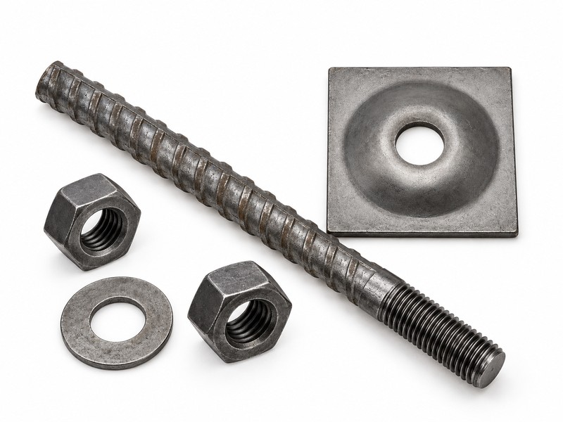
Your RFQ should define monitoring objectives, instrument coverage, data delivery, commissioning checks, and ongoing support responsibilities. Instrumented rock bolts require a working measurement package rather than a bar with an unexplained cable. Request evidence for the proposed assembly instead of assuming every sensor option suits mine conditions.
Send a reviewable scope
Make the handover practical. Include one example location, its required outputs, and expected operational events. Ask bidders to return coverage drawings, calibration documentation, environmental suitability evidence, and a sample data export. Have project personnel assess equipment suitability for the actual mine environment, including electrical and access requirements.
- Attach the monitoring decision register and location schedule.
- Request a commissioning demonstration and channel-health checks.
- Specify file ownership, export formats, revision control, and support contacts.
Close the open interfaces
| Closure check | Action to retain |
|---|---|
| 1 | Attach the monitoring decision register and location schedule. |
| 2 | Request a commissioning demonstration and channel-health checks. |
| 3 | Specify file ownership, export formats, revision control, and support contacts. |
Identify who supplies bolt hardware, sensors, acquisition equipment, software, and engineering interpretation. Ask each party to acknowledge its interface obligations before purchase. For a discussion of identifiable support hardware within your monitoring package, contact us with drawings and the proposed responsibility schedule.
Q1: Can I calculate force from any strain reading? Only with an appropriate calibration and interpretation model. Section properties, material response, sensor position, and loading mode affect that calculation.
Q2: How do I know if a quiet channel means stable loading? Check channel health first. A disconnected or damaged sensor can also produce missing or misleading observations.
Q3: Can instrumented bolts replace ground inspections? No. They provide selected measurements within a wider project monitoring and engineering process.
Q4: What’s the best number of monitored bolts? There is no universal count. Your engineer should select locations and redundancy around stated questions and geological coverage.
Q5: Should I retain old baseline files? Yes. Previous references help reviewers reconstruct changes after resets, processing revisions, or delayed installation readings.