
Dynamic testing of rock bolts examines reinforcement response under rapid loading within a defined laboratory arrangement. Two reports can list similar energy values while applying that energy through different mechanisms. Compare their methods before comparing outcomes. Identify proposed steel reinforcement hardware separately from any laboratory configuration or claimed dynamic capability.
1. What decision should a dynamic test comparison support?
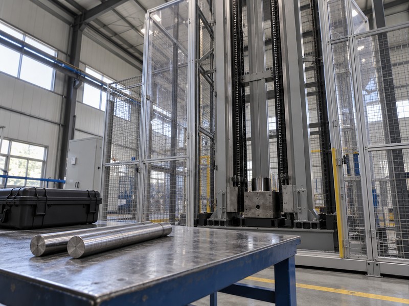
A dynamic test comparison should determine whether reported evidence answers the same loading question for a proposed application. Dynamic testing of rock bolts uses arrangements that can differ substantially. A shared unit of energy does not establish equivalent loading or deformation behavior.
Define the comparison question
Compare the experiment first. Decide whether you are comparing laboratory methods, evaluating one proposed assembly, or requesting additional evidence. Published drop-testing reviews distinguish direct-impact and momentum-transfer arrangements. That distinction provides a starting point for your matrix, rather than a shortcut for declaring one method universally superior.
- State which engineering question the reports must address.
- List quantities you intend to compare.
- Identify differences requiring specialist interpretation before ranking.
Comparison-purpose record
Use bolt-family information only for hardware context. Ask your engineer to approve the comparison task and its limits.
| Review purpose | Required evidence | Buyer decision |
|---|---|---|
| Method review | Loading arrangement descriptions | Comparable experiments? |
| Assembly evaluation | Identified tested hardware | Relevant proposed configuration? |
| Evidence-gap review | Missing test conditions | Additional information needed? |
Key takeaway: define a comparison before scoring products. Similar headline quantities can describe materially different experiments.
2. How does loading method change the experiment?
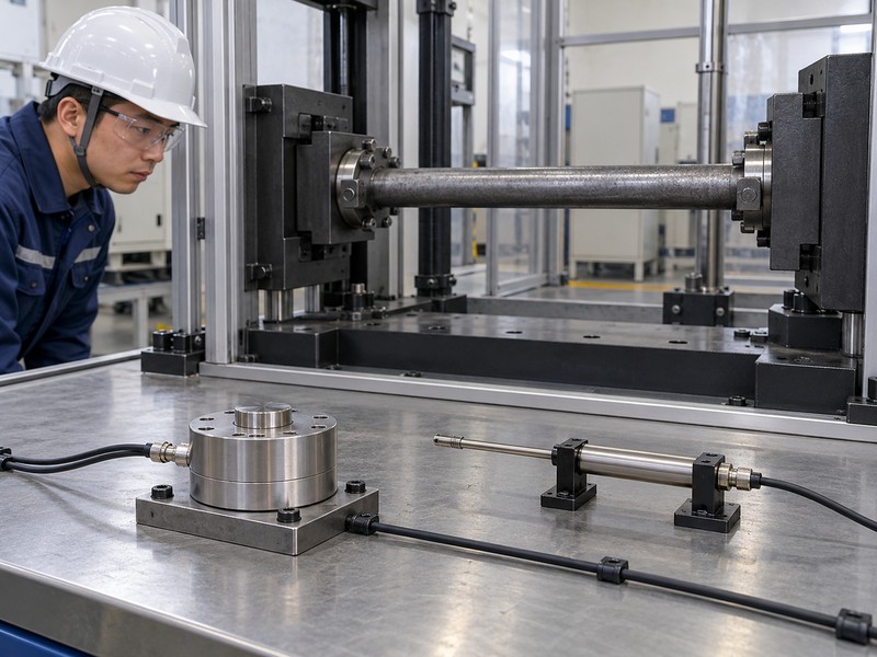
Loading method changes how moving masses, fixtures, and the specimen interact during impact. Direct-impact and momentum-transfer descriptions should be supported by an apparatus drawing. The laboratory should explain the load path for its actual arrangement.
A moving fixture can participate in motion before the specimen reaches its peak resistance. An energy figure calculated from an initial drop therefore needs a stated transfer model. Instrumented specimen response provides a different observation from nominal input conditions.
Follow moving and reacting parts
Trace the first contact. Identify what initially moves, what strikes or transfers motion, and how force reaches the bolt. Ask which components can store or dissipate energy outside the specimen. A method name without a load-path description leaves reviewers guessing about those interactions.
- Record moving masses and the stated impact arrangement.
- Identify fixtures participating in motion or reaction.
- Ask which measured quantities describe specimen response directly.
Loading-method comparison
Include head and bearing hardware where those parts enter the force path. Ask the laboratory to mark loaded interfaces on its drawing.
| Method detail | Record | Comparison concern |
|---|---|---|
| Initial motion | Apparatus description | Different energy-transfer process |
| Force path | Contact and reaction interfaces | Different loaded components |
| Participating fixtures | Moving and fixed parts | Energy outside specimen |
Key takeaway: compare load paths explicitly. Do not infer equivalent conditions from similar photographs of drop towers.
3. Which specimen dimensions and components matter?
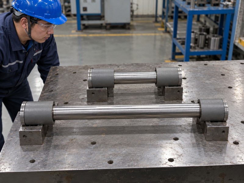
Specimen dimensions and components matter when they change the length, section, or interfaces participating in deformation. Report identity should include tested length, anchorage arrangement, and relevant hardware. A product name alone does not define the specimen.
Record the tested assembly
Keep the free length visible. Drawings should distinguish overall length from the length available for deformation within the test. Identify nuts, plates, couplers, sleeves, and other participating parts. Avoid assigning results to a different configuration merely because its bar material has the same grade label.
- Record bar or tube geometry and supplied condition.
- Identify anchorage zones and available deformation length.
- Match included accessories with their drawing revisions.
Specimen identity matrix
For hollow-bar assemblies, document any joints and section changes. Ask the reviewer to identify which differences prevent direct comparison.
| Specimen feature | Evidence | Potential consequence |
|---|---|---|
| Deformation length | Apparatus and specimen drawing | Different displacement response |
| Section geometry | Identified bar or tube | Different mechanical response |
| Components | Complete assembly schedule | Different failure location |
Key takeaway: compare complete specimen identities. Results for one configuration do not automatically establish another configuration’s dynamic rating.
4. Why do anchorage and boundaries need detail?
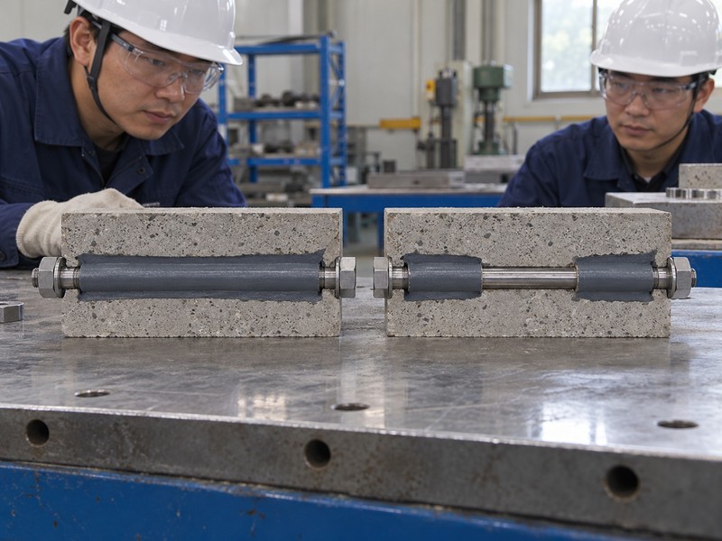
Anchorage and boundaries need detail because they control restraint, load transfer, and possible deformation outside the steel element. A rigid laboratory fixture represents a specific condition. Its response does not reproduce every underground interface.
A load–displacement record can include several deforming regions in series. If anchorage slips or the reaction arrangement moves, measured travel may exceed deformation within the steel. Identify those regions before assigning integrated work to the specimen.
Describe restraint rather than assuming it
Mark every restrained region. Identify bonded length, mechanical gripping, confining sleeves, surrounding medium, and fixture stiffness where relevant. Ask the laboratory which parts may slip, crush, or deform during a test. Record those mechanisms without attributing all measured movement to the bolt itself.
- Document anchorage preparation and relevant curing records where applicable.
- Identify the surrounding medium and specimen confinement.
- Record observable slip or fixture movement during testing.
Boundary-condition comparison
Include relevant accessory interfaces in the restraint drawing. Have your engineer review whether boundaries fit the intended comparison.
| Boundary feature | Record | Interpretation limit |
|---|---|---|
| Anchorage | Geometry and preparation | Different load transfer |
| Surrounding medium | Identified material and confinement | Different deformation mechanisms |
| Fixture restraint | Loaded and fixed interfaces | Movement outside specimen |
Key takeaway: record restraint alongside loading. A displacement value needs a defined physical location and boundary condition.
5. Which energy values should remain separate?
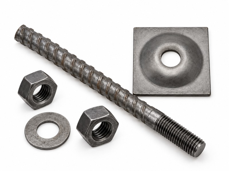
Keep nominal input energy, measured transferred energy, and calculated specimen work separately labeled where reported. They describe different parts of an experiment. Dynamic testing of rock bolts cannot be reduced to an unlabeled energy figure.
Ask how each value was obtained
Follow the energy accounting. A stated drop condition may describe available input, while integrated force–displacement data describe work under a defined measurement arrangement. Ask which losses and non-specimen effects the report includes or excludes. Request equations and sign conventions without assuming a perfect transfer of input energy.
- Record whether energy is nominal, measured, or derived.
- Identify force and displacement channels used in integration.
- Preserve any assumptions about losses or fixture participation.
Energy-label review
Keep site support context separate from laboratory accounting. Do not infer a site rating from a nominal drop-energy label.
| Reported energy | Required explanation | Unsupported shortcut |
|---|---|---|
| Input | Calculation or measurement basis | Equal to specimen absorption |
| Transferred | Defined measurement arrangement | Identical across methods |
| Integrated work | Channels and integration limits | Universal product rating |
Key takeaway: compare like energy quantities. Ask for clarification whenever a report uses energy without a defined calculation basis.
6. How should load and displacement be compared?
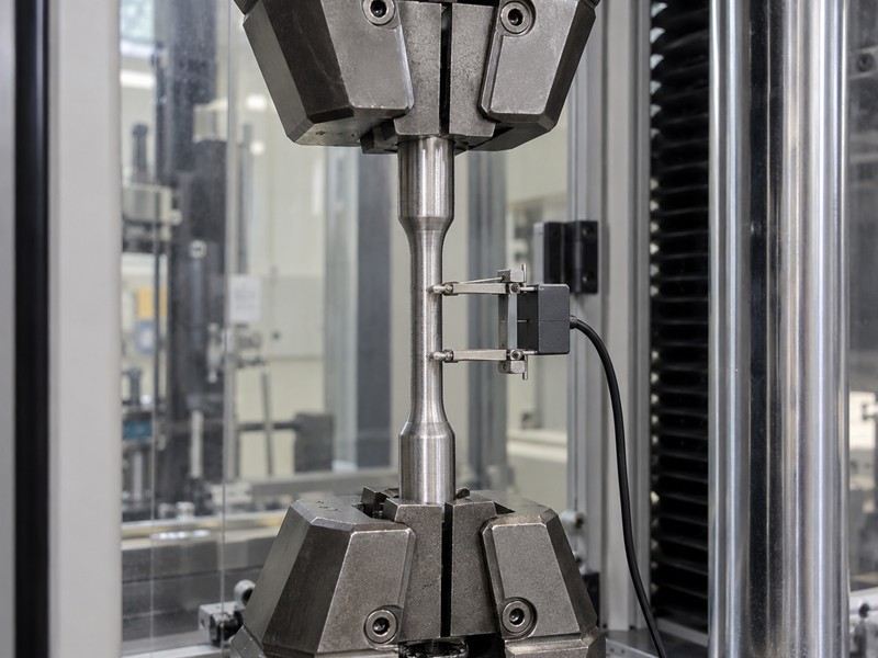
Review force-calibration scope before accepting a static calibration as evidence for dynamic impact measurements. Peak load and maximum displacement may occur at different times. Their meaning depends on how the experiment records specimen and fixture motion.
Request synchronized histories
Read the full response. Ask for force–time, displacement–time, and relevant force–displacement records where available. Preserve filtering choices and acquisition information needed for review. A single peak table can hide early slip, oscillation, fixture movement, or changes during later impact stages.
- Identify sensor locations on the apparatus drawing.
- Record sampling and processing information from the laboratory.
- Preserve original records alongside presentation plots.
Response-data review
A friction bolt configuration may involve different movement mechanisms from a bonded assembly. Compare reported mechanisms before interpreting displacement as steel elongation.
| Quantity | Location required | Review question |
|---|---|---|
| Force | Sensor position | Which interface was measured? |
| Displacement | Reference points | Specimen motion or fixture motion? |
| Peak summary | Timing and processing | Same event and definition? |
Key takeaway: request histories and locations. A summary table should remain traceable to measured response rather than replace it.
7. What should failure observations explain?
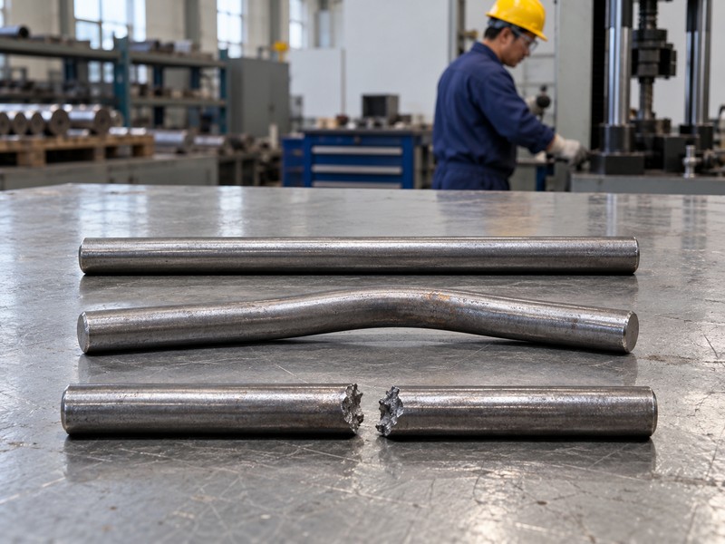
Failure observations should explain what changed, where it changed, and how that observation relates to the measured response. Fracture, slip, anchorage movement, or accessory deformation describe different mechanisms. Reports should avoid combining them under an unexplained failure label.
Inspect the entire tested assembly
Follow the weakest observed link. Ask for photographs before and after testing and a description of visible damage. Identify whether the reported endpoint was specimen rupture, a displacement limit, equipment interruption, or another criterion. A stopped test does not necessarily establish ultimate resistance.
- Record damage location against the specimen drawing.
- Describe fixture or anchorage changes alongside steel damage.
- Preserve the laboratory’s stated test endpoint.
Endpoint interpretation
Keep static pull-test records separately identified when supplied. Their loading history and endpoint may answer another question.
| Endpoint | Record needed | Interpretation caution |
|---|---|---|
| Steel rupture | Location and photographs | Configuration-specific result |
| Slip or interface movement | Observed interface | Different deformation mechanism |
| Test stopped | Stopping criterion | Ultimate capacity may remain unknown |
Key takeaway: review mechanisms with numbers. A large displacement carries little meaning without knowing what moved and why the test ended.
8. How should repeated impacts be documented?
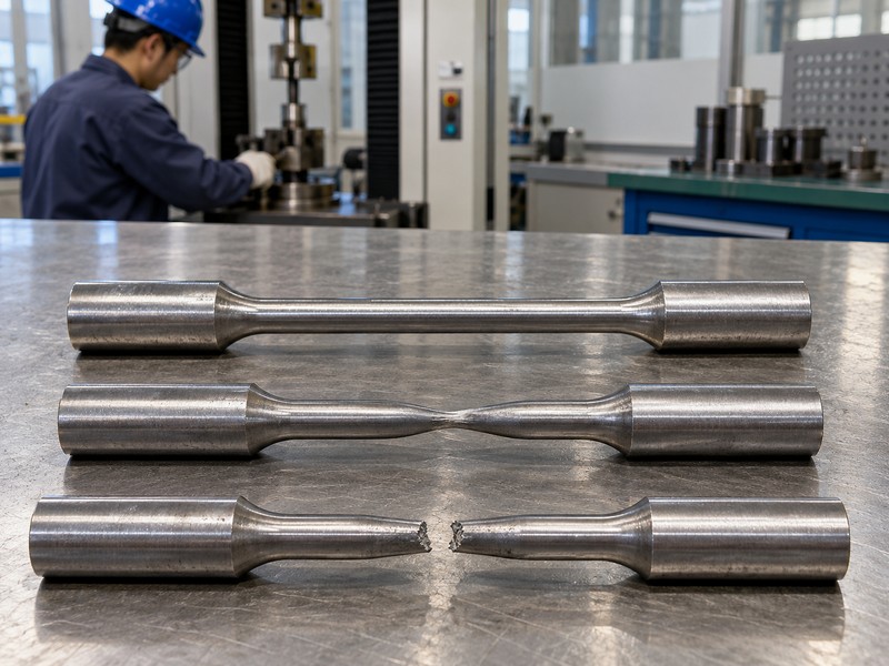
Document each impact separately with its sequence, preceding condition, settings, and observed response. Repeated impacts involve an evolving specimen state. Adding their nominal energies together does not automatically establish an equivalent single-impact capacity.
Preserve sequence effects
Keep each event distinct. Ask whether the same specimen remained installed and which adjustments occurred between impacts. Record residual deformation, visible damage, and any instrument reset. Compare each event within that history rather than presenting only a cumulative headline number.
- Identify specimen continuity across the sequence.
- Record regripping, retightening, or changed test settings.
- State which impacts met the laboratory’s quality requirements.
Impact-sequence record
Have your reviewer distinguish repeated discrete impacts from continuous cyclic fatigue experiments. These work tasks need different parameter records and interpretation.
| Sequence field | Record | Review purpose |
|---|---|---|
| Event order | Separate impact identifier | Preserve loading history |
| Between-event change | Adjustment and condition | Explain response changes |
| Cumulative figure | Defined calculation | Avoid unsupported equivalence |
Key takeaway: retain event-level results. A cumulative figure needs a qualified explanation before entering a product comparison.
9. When are two reports insufficiently comparable?

Reports are insufficiently comparable when unrecorded or materially different methods prevent a defensible interpretation of their results. Differences do not make either test useless. They can mean that direct ranking requires additional evidence or specialist analysis.
Use a comparison status
Record the unresolved mismatch. Classify each parameter as matched, different but interpretable, or unknown. Ask the engineering reviewer which differences block a comparison. Request original data or an additional matched test where justified rather than forcing unlike reports into one score.
- Compare loading method and specimen configuration before numerical outcomes.
- Identify missing boundary and measurement details.
- Retain the rationale behind each comparison decision.
Comparability matrix
Provide this matrix alongside bid summaries so decision makers can see evidence limits. Do not hide unknown conditions behind a low confidence score alone.
| Status | Evidence condition | Procurement treatment |
|---|---|---|
| Matched | Relevant conditions align | Qualified numerical comparison |
| Different | Effects explained by reviewer | Compare with stated limits |
| Unknown | Required details missing | Request clarification |
Key takeaway: let unknowns remain visible. A reviewable evidence gap is more useful than a ranking without a defensible basis.
10. What should your dynamic-test enquiry request?
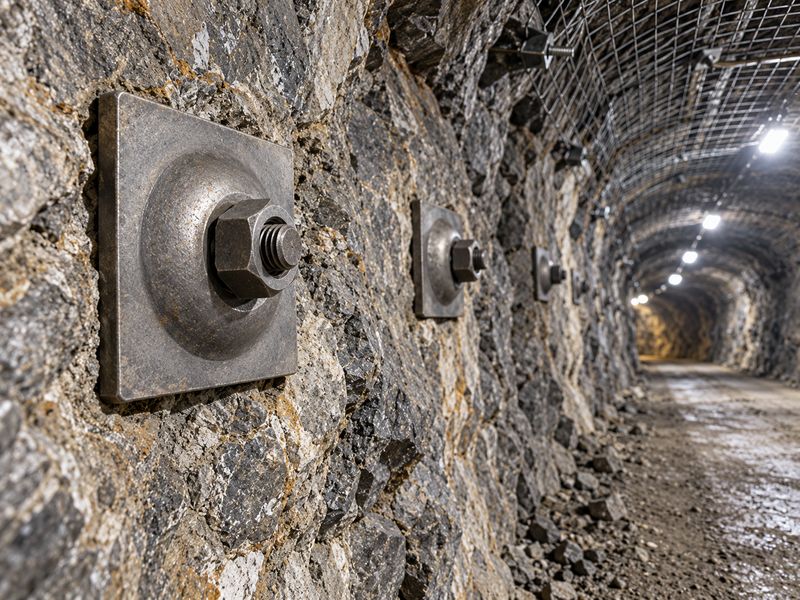
Your enquiry should request apparatus descriptions, specimen identity, boundary conditions, measured histories, energy definitions, and documented endpoints. Dynamic testing of rock bolts needs that evidence before a buyer can compare results. Specify the engineering decision and ask laboratories to propose a suitable test program.
Request comparable evidence deliberately
Send the matrix with the sample. Identify the proposed assembly and the quantities your team intends to review. Ask the laboratory to explain method suitability and limits. Request individual results and deviations without inventing a universal impact sequence or acceptance value.
- Attach drawings and complete assembly identification.
- Require separate labels for input energy and derived specimen work.
- Ask for event histories, photographs, and a qualified interpretation.
Keep product claims within supplied evidence
| Closure check | Action to retain |
|---|---|
| 1 | Attach drawings and complete assembly identification. |
| 2 | Require separate labels for input energy and derived specimen work. |
| 3 | Ask for event histories, photographs, and a qualified interpretation. |
For a discussion of identifiable steel support hardware, contact us with your test enquiry and drawings. Request product-specific evidence before assigning a dynamic rating or assuming availability of a particular energy-absorbing design.
Q1: Can I rank bolts by their largest reported energy number? Only after establishing comparable quantities and conditions. Different methods can report different forms of energy.
Q2: How do I know whether displacement means steel elongation? Check measurement locations and observed mechanisms. Fixtures, anchorage, and interfaces may also move.
Q3: What’s the best response to missing apparatus details? Request clarification. Keep numerical comparisons qualified until a reviewer understands the actual load path and boundaries.
Q4: Can I add repeated impact energies into one capacity? No automatic equivalence applies. Preserve event history and ask for the stated calculation and interpretation limits.
Q5: Does this article specify a fatigue test program? No. Continuous cyclic loading requires its own parameters and damage assessment outside this impact-method comparison.