
Rock bolt tensile testing measures a defined steel specimen’s response during axial tension under stated laboratory conditions. A certificate listing strength and elongation can still omit the specimen geometry needed for comparison. Read those definitions before accepting a material claim. Identify proposed steel bolt hardware separately from the particular specimen that produced each result.
1. What does a material tensile test establish?
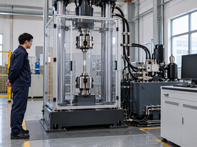
A material tensile test establishes strength and deformation observations for its specimen and method, rather than installed anchorage capacity. Rock bolt tensile testing may concern a machined sample or another defined steel specimen. The report must identify which one.
Separate material evidence from system behavior
Start with the specimen. Laboratory tension methods characterize steel under uniaxial loading. A specimen removed from a product may not represent every feature of the finished assembly or its service environment. A partially embedded assembly experiment also includes load-transfer effects, so its result should retain that scope.
- Identify whether testing concerns material, a finished item, or an embedded assembly.
- Keep specimen identity connected with the reported properties.
- Request separate evidence for installation-specific engineering questions.
Evidence-scope table
Use bolt-family descriptions for initial naming only. Ask the laboratory to state its tested object clearly.
| Tested object | Evidence provided | Limit to preserve |
|---|---|---|
| Material specimen | Defined tensile properties | Specimen and method scope |
| Finished component | Its tested response | Particular geometry and fixtures |
| Embedded assembly | Combined assembly behavior | Material and interface effects |
Key takeaway: identify what was tested. A material result cannot automatically become an installed support rating.
2. How does specimen geometry affect interpretation?
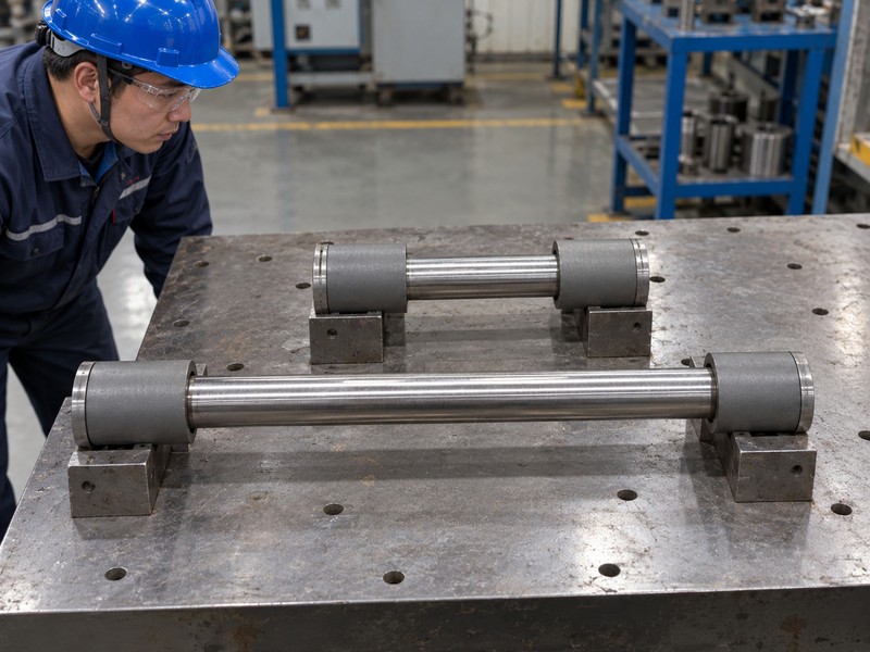
Specimen geometry affects stress calculation, deformation measurement, and the region represented by the result. Machining can remove threads, ribs, or surface condition from a sample. Full-section specimens retain different geometric features and require an appropriate test basis.
Read the preparation record
Look at what was removed. Ask where the sample came from and how its test section was prepared. A machined smooth section may characterize underlying material without testing a finished thread root. Preserve orientation and sampling location where relevant. Do not assume specimens are equivalent because their steel grade labels match.
- Record specimen type and relevant dimensions.
- Identify source position and preparation method.
- Distinguish retained product features from machined surfaces.
Geometry-review schedule
For hollow-bar material, confirm whether evidence concerns a tube section or a prepared specimen. Ask the reviewer to establish the appropriate interpretation.
| Geometry field | Review question | Consequence |
|---|---|---|
| Preparation | Which features remain? | Material or product-feature scope |
| Test section | Which dimensions apply? | Stress calculation basis |
| Sampling location | Which material was sampled? | Product representation |
Key takeaway: preserve specimen drawings with reports. A familiar material name does not resolve differences in test geometry.
3. Why must force and stress remain distinct?
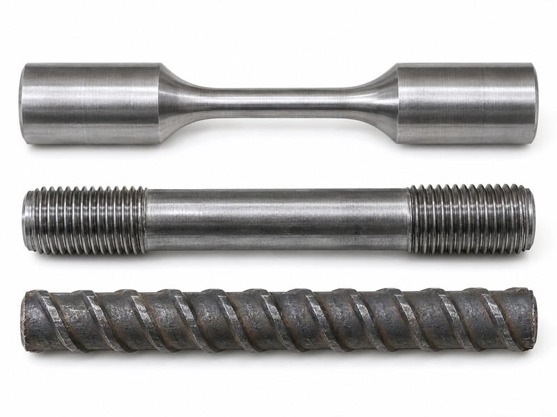
Force and stress must remain distinct because stress relates force to a stated cross-sectional area. A larger section can carry more force without having higher material strength. Reported stress becomes ambiguous when its area basis is missing.
Check the denominator before comparing strength
Find the original area. Engineering stress uses original specimen cross-sectional area. Ask how that area was established for the relevant profile. A nominal outside diameter may not describe a hollow section or a threaded test region adequately. Avoid inventing a tensile-stress area from catalogue dimensions without the applicable method.
- Preserve original force observations and reported stress values.
- Record area definition and measured specimen dimensions.
- Compare equivalent quantities with consistent units.
Force-and-stress review
Include component identity where a report concerns a separate threaded item. Ask the laboratory to explain its calculation basis.
| Quantity | Meaning | Required basis |
|---|---|---|
| Force | Axial load carried | Measurement and units |
| Engineering stress | Force divided by original area | Defined specimen area |
| Reported strength | Specified tensile-test result | Method and specimen identity |
Key takeaway: compare stress with stress and force with force. Preserve the area basis before drawing material-strength conclusions.
4. What does the reported yield result mean?
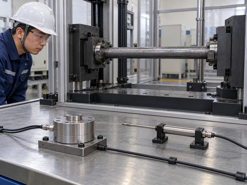
The reported yield result describes a method-defined transition associated with permanent deformation, using the procedure stated by the laboratory. Some materials show a distinct yield feature, while others require a defined calculation. Its label should make that distinction clear.
Read the yield definition beside its value
Do not assume one calculation. Ask whether the report uses a yield point, an offset proof result, or another applicable method-defined quantity. Preserve any offset or extension criterion explicitly when specified. This article supplies no universal offset value or steel acceptance limit.
- Identify the yield quantity by its complete reported name.
- Record strain measurement and calculation basis.
- Ask how unclear or irregular curve features were handled.
Yield-result definitions
A bearing plate material record may concern another specimen and product requirement. Keep results mapped to the relevant item.
| Yield field | Evidence needed | Comparison risk |
|---|---|---|
| Quantity name | Full report terminology | Unlike definitions combined |
| Calculation criterion | Applicable stated method | Unstated offset assumed |
| Strain measurement | Instrument and reference length | Unsupported curve interpretation |
Key takeaway: compare defined yield results. A shortened label can hide a different calculation or measurement basis.
5. How should ultimate strength and necking be read?
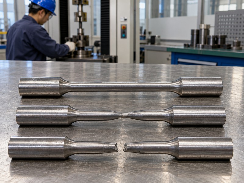
Ultimate tensile strength identifies the maximum engineering stress reached during the stated test, while necking describes localized section reduction in suitable ductile specimens. A falling engineering curve after its peak does not mean every local stress decreases. Read the reported quantity within its definition.
Keep engineering and local behavior separate
Watch where deformation concentrates. Once deformation localizes, a single original-area calculation cannot describe every local condition at the narrowed section. Ask the laboratory to distinguish maximum force, reported tensile strength, and fracture observations. A procurement comparison usually needs the method-defined result rather than an improvised true-stress reconstruction.
- Identify the maximum-force observation used for reported strength.
- Preserve photographs showing any necked region.
- Keep fracture load separately labeled where supplied.
Peak-result review
Your tunnel support context does not change these measurement definitions. Let qualified engineers determine how material data enter design.
| Observation | Report meaning | Do not assume |
|---|---|---|
| Maximum force | Peak axial load | Same as fracture load |
| Tensile strength | Method-defined peak stress | Installed capacity |
| Necking | Localized deformation | Uniform strain everywhere |
Key takeaway: retain peak and fracture information separately. They describe different stages within a tensile experiment.
6. Why does elongation need a gauge length?
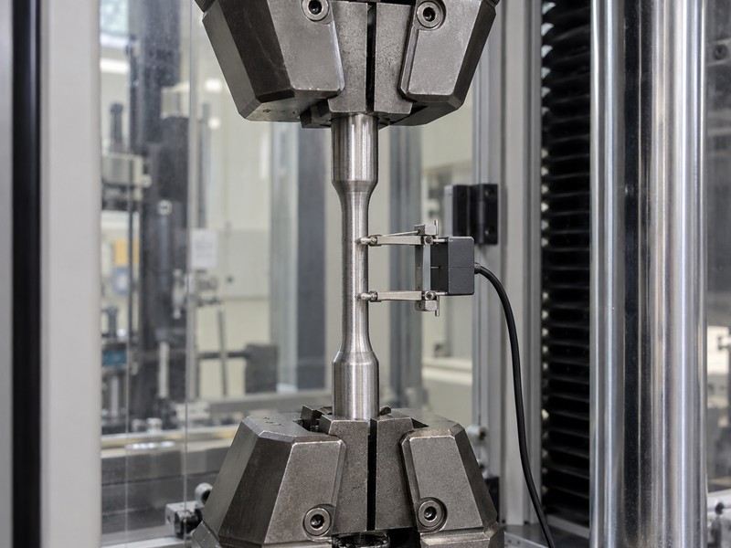
Elongation needs a gauge length because reported extension is related to a defined original measurement length. Localized deformation can occupy different proportions of different gauge lengths. Results therefore need their specimen and measurement definitions before comparison.
Identify the actual deformation measurement
Check the reference length. Ask whether the result describes elongation at a defined stage or elongation measured after fracture. Machine travel can include grip and apparatus movement, so it should not be relabeled as specimen elongation without justification. Preserve the laboratory’s method and gauge definition.
- Record original gauge length and specimen type.
- Identify extensometer readings or post-fracture measurements as applicable.
- Keep machine displacement separately named.
Elongation-comparison table
A friction bolt tube may use different specimen preparation from a solid steel bar. Obtain the actual test description rather than borrowing another item’s elongation result.
| Measurement | Required definition | Comparison concern |
|---|---|---|
| Specimen elongation | Gauge length and test stage | Different reference lengths |
| Post-fracture result | Measurement procedure | Localized deformation contribution |
| Machine travel | Apparatus reference points | Grip and frame movement |
Key takeaway: compare elongation with matching definitions. A percentage without gauge information can conceal a materially different measurement.
7. What do fracture location and validity add?
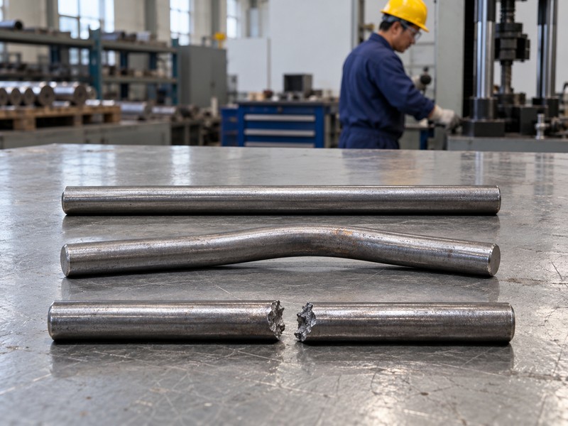
Fracture location and validity observations help establish whether a result represents the intended specimen region under the applicable method. A grip-related problem differs from fracture within the measured section. The laboratory should explain its validity decision rather than leaving you to infer one.
Inspect the specimen after the number
Locate the break. Request photographs showing fracture relative to gauge features, grips, threads, and any preparation changes. Ask the laboratory to describe slip, misalignment, or unusual fracture observations. Acceptance and retest decisions require the applicable method and product specification, not a generic rejection rule from this article.
- Retain photographs with specimen identification.
- Record fracture position and observed necking.
- Preserve validity statements and reasons for repeated tests.
Fracture-review record
Keep field pull-test observations separately labeled. Their potential failure interfaces differ from a material specimen’s gauge region.
| Observation | Record | Review purpose |
|---|---|---|
| Fracture location | Relative to specimen features | Intended-region interpretation |
| Grip or slip issue | Laboratory observations | Test validity review |
| Repeated test | Reason and original result | Transparent evidence history |
Key takeaway: keep unsuccessful and repeated runs traceable. A favorable replacement value should retain its relationship with the original observation.
8. How do you compare reports from different laboratories?

Compare laboratories by matching specimen preparation, method, area basis, yield definition, elongation measurement, and reported conditions. Similar headings do not establish identical tests. Differences should be resolved before interpreting small variations as changes in material quality.
Reconcile definitions before comparing values
Build one results legend. Map each laboratory’s terminology onto clearly defined quantities. Identify differences in testing temperature, loading rate, and specimen preparation where reported. Ask a qualified reviewer whether those differences affect your intended comparison. Do not rank material lots using a mixture of incompatible result definitions.
- Match specimen geometry and source identity.
- Align force, stress, and deformation terminology.
- Record missing conditions and unresolved comparison limits.
Laboratory-comparison matrix
Keep original reports unchanged and add a separate review sheet. That preserves each laboratory’s findings while making comparison assumptions visible.
| Comparison layer | Match needed | If different |
|---|---|---|
| Specimen | Preparation and geometry | Qualify representation |
| Quantity | Same physical definition | Reconcile terminology |
| Conditions | Relevant reported settings | Obtain specialist interpretation |
Key takeaway: compare definitions before differences. A small numerical gap can be less informative than an unresolved measurement mismatch.
9. How should results connect with delivered steel?
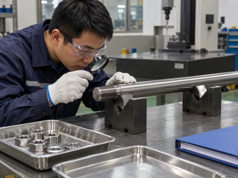
Connect results with delivered steel through documented specimen origin, material identity, production or shipment references, and the applicable sampling basis. A genuine laboratory report may still concern another material group. Traceability determines what your file can support.
Follow the sample back to stock
Trace one certificate line. Identify the tested sample and the finished items it represents under your purchase requirements. Ask how identities survive cutting, processing, packaging, and shipment. Sampling rules belong to the applicable specification and inspection plan; this article does not invent a universal specimen count.
- Preserve source identifiers and specimen references.
- Match delivered lots with relevant test records.
- Flag unidentified or mixed stock for authorized review.
Material-traceability chain
Have quality personnel check this chain before accepting result summaries. Resolve identity gaps even when every listed value appears favorable.
| Chain element | Evidence | Potential gap |
|---|---|---|
| Specimen origin | Sampling reference | Unknown sampled material |
| Product connection | Production or lot mapping | Different finished stock |
| Delivery | Shipment identity | Certificate unrelated to order |
Key takeaway: a result applies through its identity chain. Confirm that connection before using tensile data for shipment acceptance.
10. What should your tensile-report request specify?
Your request should specify the product identity, intended specimen scope, applicable method, required result definitions, and traceability deliverables. Rock bolt tensile testing becomes useful when buyers can reconstruct how each property was obtained. Ask qualified personnel to select applicable acceptance criteria.
Request a complete material result
Make the report interpretable. Ask for specimen geometry, original area basis, yield definition, tensile strength, and elongation details. Request fracture observations, deviations, and individual results. Keep installed anchorage, shear, fatigue, and assembly-interface questions within their own evidence scopes.
- Include product drawings and material identification requirements.
- Request method and specimen details alongside summary values.
- Require a clear connection between samples and delivered material.
Obtain evidence for the actual supply
| Closure check | Action to retain |
|---|---|
| 1 | Include product drawings and material identification requirements. |
| 2 | Request method and specimen details alongside summary values. |
| 3 | Require a clear connection between samples and delivered material. |
For a steel hardware enquiry, contact us with your drawings and tensile-report requirements. Request available material evidence before making strength or ductility claims about a proposed order. Have your technical reviewer resolve missing definitions before acceptance.
Q1: Can I compare force values from different bar sizes? Only with geometry context. Force and material stress describe different quantities, so section differences need explicit treatment.
Q2: How do I know what an elongation percentage means? Check gauge length, specimen type, and measurement stage. A percentage alone omits the reference behind the result.
Q3: What’s the best way to interpret an unclear yield label? Ask the laboratory for its complete definition and calculation basis before comparing that result with another report.
Q4: Can a material tensile report certify installed anchorage? No. Installed resistance also involves the actual assembly, anchorage, surrounding medium, and project-specific conditions.
Q5: Should fracture photographs accompany the report? Yes, where available. They help reviewers understand location, necking, unusual observations, and the laboratory’s validity assessment.