
Self drilling anchors fit limited headroom through planned short-bar sections, compatible connections and equipment with a workable drilling envelope. Restricted clearance can leave a full-length bar impossible to handle even when a rig fits underground. For an inquiry labeled “self drilling anchors limited headroom,” assess every handling movement before choosing section lengths. Start with your proposed hollow-bar anchor system and a measured work area. A compact rig alone does not prove that a complete assembly can be installed.
1. What does limited headroom mean for anchor planning?

Limited headroom means available clearance restricts some part of equipment positioning, bar handling or connection work. A roof measurement captures only one dimension of that problem. Drilling inclination, floor conditions and nearby services also shape usable space. Measure the actual operating envelope rather than relying on a tunnel’s nominal height.
Which spaces should your survey capture?
Measure each movement within the proposed drilling position. Include machine setup, feed travel and material presentation. A bar that fits on a transport rack may still obstruct connection work at an inclined drive head. Keep separate measurements for storage and operation.
- Measure clearance above and beside the rig.
- Note nearby pipes, cables and structural obstructions.
- Map handling paths from storage to drive head.
How should you document restrictions?
Add a marked-up clearance drawing to your inquiry for anchor accessories. Identify each measurement datum and proposed drilling orientation. Ask your equipment specialist to review movements that a static drawing cannot establish.
| Clearance zone | What to record | Planning consequence |
|---|---|---|
| Machine envelope | Actual positioned dimensions | Setup feasibility |
| Bar handling | Unobstructed transfer path | Section length choice |
| Connection zone | Tool and hand access | Assembly practicality |
A useful survey follows work movements rather than one height.
2. Why can shorter hollow bars help?
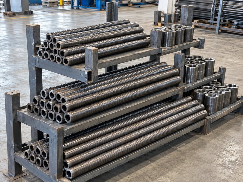
Shorter hollow bars reduce individual handling length while compatible connections extend the planned assembly. Manufacturer hollow-bar information identifies connections and smaller equipment as options for restricted headroom. That principle supports planning with short sections. It does not establish unlimited extension or acceptance of arbitrary connectors.
What tradeoff accompanies shorter sections?
Count connection work alongside handling clearance. More sections can introduce more connection tasks and additional interfaces requiring control. Procurement should compare those tasks with available access and approved assembly requirements. A short section solves only part of a restricted-space problem.
- Confirm available section lengths through documentation.
- Count connections within each proposed assembly.
- Check handling and access at every connection.
Which product information should you request?
Request section drawings and matched connector information for your self-drilling anchor components. Keep proposed total length within project design documents. Review European connection-assessment guidance for proposed hollow-bar connections without treating it as proof of installation clearance.
| Planning choice | Potential benefit | Additional review |
|---|---|---|
| Shorter sections | Easier presentation | More connection work |
| Longer sections | Fewer connections | Greater handling clearance |
| Mixed lengths | Fit varying positions | Clear assembly schedule |
Choose a section schedule after checking both space and interfaces.
3. Which rig dimensions matter beyond machine height?

Feed travel, drive-head position and positioning movement matter alongside machine height. A parked machine can fit beneath a roof while its working arrangement cannot. Equipment drawings should show the drilling configuration used for your assessment. Include attachments and adaptors within that review.
How can equipment documents mislead planning?
Use operating dimensions instead of transport dimensions. Transport height may describe folded equipment with a different orientation. Ask the equipment supplier which drawing represents your actual drilling position. Check access for controls, maintenance and safe material presentation within project procedures.
- Obtain positioned equipment dimensions.
- Identify usable feed stroke for each section.
- Include drive adaptors and connection hardware.
What should an equipment review deliver?
Ask for a coordinated layout linking rig position with your section schedule. Our self-drilling system background offers adjacent terminology; current machine documents must establish clearances. Record unresolved movements for physical verification before field release.
| Equipment record | Planning question | Required output |
|---|---|---|
| Transport drawing | Can equipment reach location? | Access confirmation |
| Operating drawing | Can equipment perform work? | Positioned layout |
| Feed information | Can each section advance? | Compatible section schedule |
Transport access and operating feasibility need separate checks.
4. How do you plan space for each connection?

Plan enough space for connector presentation, specified assembly work and inspection at each connection point. Nominal bar clearance cannot establish tool access. Surrounding services or machine structure may obstruct a connector after drilling advances. Review repeated connection work within the actual working position.
What should a connection access check include?
Follow a connector through its full working sequence. Consider where an operator presents a section and where tools must approach. Use approved assembly instructions for engagement details. This planning check should never replace product-specific installation requirements.
- Locate connection points relative to machine structure.
- Check access for specified tools and inspection.
- Identify a protected staging position for sections.
How should purchasing control the result?
Attach the accepted connection layout to your hollow-bar product request. Require review when a proposed connector changes dimensions or assembly access. Keep clearances documented so an alternate part cannot enter through a purchase description alone.
| Connection concern | Evidence needed | Buyer response |
|---|---|---|
| Tool access | Positioned layout or mock-up | Confirm workable sequence |
| Connector size | Controlled component drawing | Check spatial fit |
| Assembly change | Revised compatibility review | Hold substitution |
Check repeated connection work before approving a section arrangement.
5. How should you divide the planned anchor length?
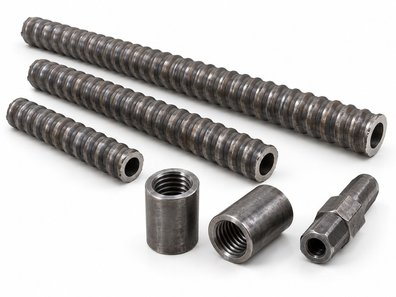
Divide the planned length using approved design requirements, available sections and demonstrated equipment clearance. A convenient shipping length should not determine a support design. Your schedule must also identify connections, final projection and any approved length adjustment. Resolve these items before creating purchase quantities.
What belongs in a section schedule?
Make the proposed assembly visible on one drawing. List each section in order and identify its matched connection. Include drawing references rather than handwritten assumptions about cutting or trimming. Any modification needs supplier and engineering acceptance where applicable.
- Identify required installed configuration and projection.
- List section order and component references.
- Mark permitted adjustments and their authority.
How do you keep quantities accurate?
Count connection accessories from the approved assembly schedule rather than a generic allowance. Keep contingency quantities separately identified. This helps purchasing see whether extra pieces cover damage, alternative layouts or approved spares.
| Schedule item | Why it belongs | Common ambiguity |
|---|---|---|
| Section sequence | Defines assembly arrangement | Mixed lengths unspecified |
| Connection count | Supports accurate ordering | Spare stock confused |
| Final projection | Links space with design | Unapproved field shortening |
Use the accepted assembly drawing as your quantity basis.
6. What can a physical clearance mock-up verify?
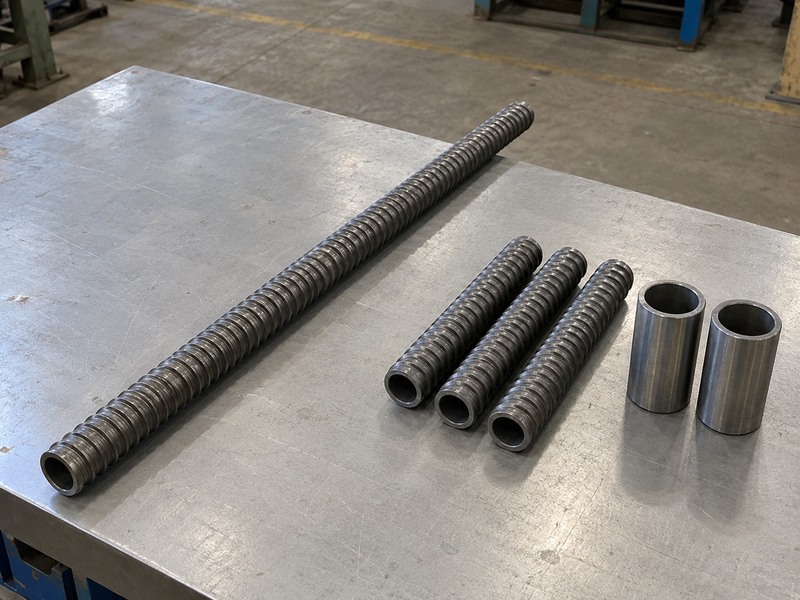
A physical mock-up can verify handling and access assumptions under representative spatial restrictions. It cannot establish geotechnical capacity or qualify an untested connection. Use full-size equipment information and representative components wherever practical. Record what your mock-up demonstrates and which conditions remain untested.
Which motions deserve a trial?
Rehearse the awkward movements before mobilization. Present a section at the proposed drilling angle and check connector access. Consider how an approved work method handles the final section. Keep the trial controlled and avoid operating equipment outside its authorized conditions.
- Present sections through the available handling path.
- Check connector and tool access with equipment stopped.
- Verify removal paths for tools and packaging.
How should you record the outcome?
Document representative dimensions, component identities and observed restrictions. Use hollow-bar background material only for adjacent reading. A mock-up approval should state its spatial scope without implying drilling or anchorage qualification.
| Mock-up finding | What it supports | What it cannot establish |
|---|---|---|
| Bar clears roof | Handling feasibility | Ground performance |
| Tools reach connector | Assembly access | Connection strength |
| Layout fits position | Spatial coordination | Every field condition |
Retain photographs with dimensions and explicit review limits.
7. How do services and working angles change clearance?

Services and working angles change the space available for equipment and material movement. A horizontal section and an inclined section occupy different handling envelopes. Nearby cables, pipes and ventilation arrangements can constrain movement further. Survey actual positions rather than assuming a clear roof plane.
What should your layout distinguish?
Map restrictions at each drilling orientation. A single clearance check may cover only one anchor position. Ask your equipment specialist which orientations need separate review. Coordinate those layouts with project controls for services and work-area access.
- Mark fixed services and protected exclusion areas.
- Record proposed inclination and drilling direction.
- Identify positions with different handling constraints.
What happens when a layout changes?
Recheck affected positions before accepting revised section lengths or equipment placement. Keep a controlled record of relocated services and changed restrictions. Notify purchasing if those revisions alter component quantities or the accepted assembly schedule.
| Field condition | Possible planning effect | Required review |
|---|---|---|
| Different inclination | Changed handling envelope | Positioned layout |
| Nearby services | Restricted movement | Coordinated access plan |
| Uneven work area | Changed machine position | Equipment setup assessment |
A clearance approval applies to its documented position and orientation.
8. What must arrive with a low-headroom component order?

A low-headroom component order should arrive with identifiable sections, matched connections and documents linking them to the approved schedule. Short bars with unclear identities can still create assembly errors. Receiving teams need information that distinguishes project layouts and product variants. Packaging organization should support those checks.
Which incoming checks protect the plan?
Sort deliveries by the accepted assembly schedule. Compare section identities and counts before material enters underground storage. Keep mixed lengths distinguishable without relying on appearance alone. Refer damaged threads or undocumented substitutions for technical disposition.
- Reconcile section lengths with controlled documents.
- Check matched connection identities and quantities.
- Preserve supplied product and lot references.
Which documents should remain accessible?
Keep self-drilling anchor order details connected with drawings and approved alternatives. Provide field teams with the current schedule through project document control. Superseded arrangements should not remain available as competing instructions.
| Delivery record | Practical purpose | Escalation trigger |
|---|---|---|
| Section identification | Prevent mixed assemblies | Unidentified material |
| Connector schedule | Preserve matched components | Alternate part delivered |
| Current layout | Maintain spatial assumptions | Different section arrangement |
Receiving checks protect a plan already accepted by engineering.
9. Which late changes need another headroom review?
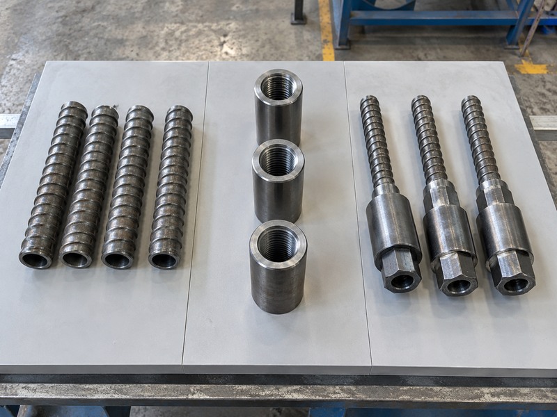
Late changes need review when they alter component length, connection geometry or operating space. A different rig attachment can invalidate a previously workable layout. A longer spare section may also create handling problems despite belonging to an approved bar family. Keep spatial acceptance separate from general product acceptance.
What should trigger a controlled revision?
Treat space-changing substitutions as technical changes. Purchasing should flag proposals affecting the operating envelope before issuing replacements. Ask the responsible team whether a new mock-up or drawing review is needed. Retain the decision with your supply records.
- Alternate section lengths or connector dimensions.
- Different drive head, adaptor or feed arrangement.
- Changed service layout or drilling orientation.
What makes a revision usable underground?
Issue a revised component schedule with clear applicability by location. List obsolete assumptions and identify affected material. Confirm that supervisors receive the accepted revision before replacement sections reach a work area.
| Proposed change | Recheck | Release evidence |
|---|---|---|
| Longer section | Handling path | Revised section schedule |
| Different attachment | Operating envelope | Equipment review |
| Moved services | Working clearances | Coordinated layout approval |
A usable revision connects changed parts with changed field conditions.
10. How do you prepare a low-headroom anchor inquiry?

Prepare an inquiry with measured restrictions, proposed equipment and an engineer-defined anchor arrangement. Include section and connector questions before requesting a commercial quote. Suppliers can then respond against an actual configuration. A vague request for short bars leaves equipment compatibility and connection access unresolved.
What should your inquiry package include?
Give the supplier a position-specific layout. Attach available drawings and state which dimensions remain provisional. Ask for component drawings and assembly restrictions that your team can review. Keep loading approval with the project engineer rather than inferring it from spatial fit.
- Measured work area and service restrictions.
- Proposed drilling orientation and rig configuration.
- Required assembly layout and accepted design references.
- Requested section, connector and documentation details.
What should you send before ordering?
| Closure check | Action to retain |
|---|---|
| 1 | Measured work area and service restrictions. |
| 2 | Proposed drilling orientation and rig configuration. |
| 3 | Required assembly layout and accepted design references. |
| 4 | Requested section, connector and documentation details. |
Send your clearance drawing, proposed section schedule and component requirements when you contact us. Ask for a documented response identifying available matching components. Approve purchase quantities after your team accepts both spatial feasibility and assembly requirements.
Q1: Can I solve limited headroom by choosing a smaller rig?
Sometimes, bar handling, connection access and feed travel still need separate checks within the proposed working position.
Q2: Can I connect short bars indefinitely?
No universal extension rule applies. Your design and matched-system documentation must accept the complete assembly.
Q3: What’s the best way to choose section length?
Use measured handling clearance and actual equipment information. Confirm the resulting layout against approved assembly requirements.
Q4: How do I know if a mock-up proves suitability?
Read its recorded scope and limitations. A clearance mock-up demonstrates spatial feasibility and cannot establish ground-support capacity.
Q5: Can I substitute a longer section during delivery?
Only after the affected layout receives review. Product-family compatibility alone does not establish available handling clearance.