
A self aligning idler guides a conveyor belt through an assembly designed to change its support response when the belt wanders. Installation must suit that mechanism. If your new unit binds or contacts an edge constantly, check placement and geometry before adjusting further. Use approved drawings and recorded belt behavior throughout the work.
1. What parts make up a self aligning idler?
A self aligning idler includes rotating support and a mechanism that permits designed corrective movement. Its exact arrangement may also include sensing rollers, links and stops. You need the complete assembly drawing because component names alone do not explain its response.
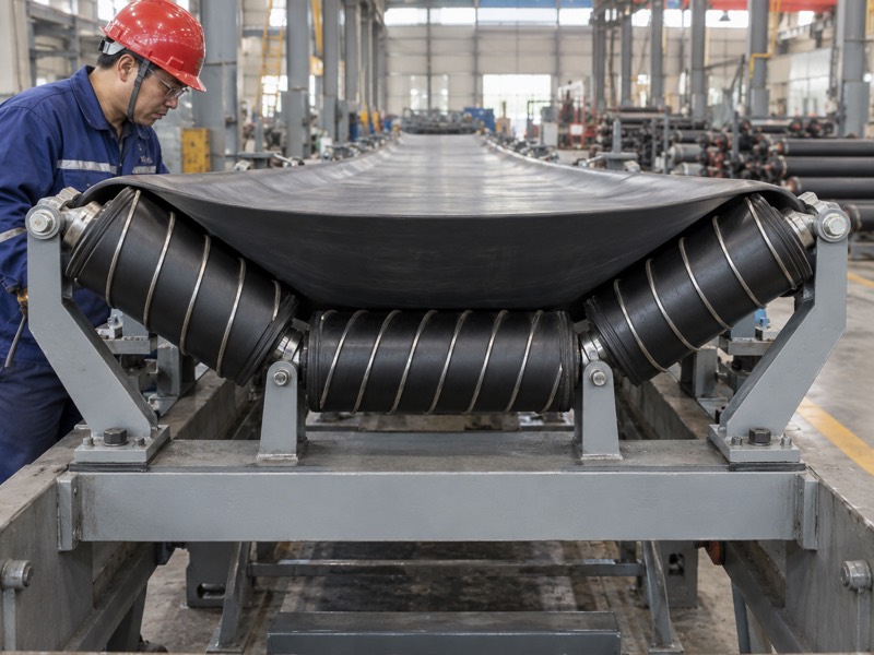
Which components should you identify?
Mark the moving and fixed parts before installation. A pivoting support frame moves relative to its mounting structure. Rollers turn within that frame. If your design uses edge sensing, its contact and linkage add separate inspection points.
- Identify support rollers, pivot interfaces and mounting brackets.
- Mark sensing components and links where present.
- Locate travel stops, guards and adjustment provisions.
Then check what your supplier includes. A roller-only order may omit parts required for a functioning assembly. Keep supply scope and installation responsibility clear so your crew does not improvise missing interfaces.
What should your assembly record show?
| Component group | Function | Record |
|---|---|---|
| Support rollers | Provide belt contact | Dimensions and arrangement |
| Pivot and links | Permit designed response | Movement and limits |
| Fixed mounting | Transfers loads to structure | Approved interfaces |
Key Takeaway: Identify the entire mechanism and supply scope. Resolve missing parts before scheduling installation.
2. How do you decide whether a location is suitable?
A suitable location meets the assembly’s requirements for belt contact, approach geometry and structural support. A self aligning idler has no universal placement rule. If your proposed location differs from approved drawings, obtain an application review before fitting it.

What site details influence placement?
Review the surrounding belt path as well as available space. Loading points, trough changes and pulley approaches can affect contact. Nearby structure may restrict pivot travel. Access and guarding also need review before a bracket is added.
- Mark adjacent supports, pulleys and loading areas.
- Confirm structural attachment and assembly movement clearance.
- Identify safe inspection access and guarding requirements.
If drift starts upstream, a new location may only hide its symptom. Record that fault before approving a device. Your placement review should state both operating duty and the limits of its corrective role.
Which location condition needs review?
| Condition | Placement concern | Approval reference |
|---|---|---|
| Changing belt profile | Contact varies | Conveyor geometry |
| Restricted space | Pivot movement blocked | Assembly envelope |
| Nearby loading disturbance | Approach changes | Operating-duty review |
Key Takeaway: Choose location through an approved application review. Include contact, movement and access on the installation sketch.
3. What should you verify before physical installation?
Verify conveyor condition, component identity, mounting readiness and approved isolation before installing a self aligning idler. Known faults should be recorded before new hardware changes belt behavior. That baseline helps you interpret later trial results.

How do you prepare the work area?
Complete the baseline before replacing support. Observe belt behavior from safe locations while normal guarding remains in place. Then follow site-approved lockout/tagout for physical work. Manage belt support and stored energy through your site’s planned procedure.
- Confirm part identity and current drawing revision.
- Inspect existing frame condition and mounting interfaces.
- Record drift, wear and contamination before removal.
If the work exposes unsupported belt spans or suspended parts, use an approved handling plan. Don’t treat a stopped drive as proof of isolation. Installation must follow responsible site procedures for the complete energy condition.
What should pre-installation checks record?
| Check | Purpose | Evidence |
|---|---|---|
| Belt baseline | Shows existing fault pattern | Observation record |
| Component identity | Avoids wrong assembly | Drawing and part record |
| Work preparation | Supports controlled installation | Approved site procedure |
Key Takeaway: Begin with a documented baseline and prepared work plan. Keep isolation and handling responsibilities clear.
4. How should carrying-side support geometry be checked?
Check carrying-side profile, elevation and mounting against the approved assembly and conveyor drawings. A self aligning idler must engage the intended belt shape. If neighboring supports differ or loading is uneven, contact can change before corrective movement begins.
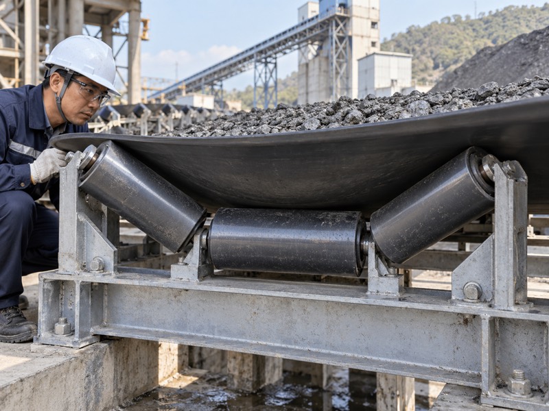
Which neighboring features should you measure?
Use one defined conveyor reference for your checks. Inspect carrying roller support around the selected location. Compare installed frame condition, profile and alignment. Then verify your proposed assembly without relying on a bent nearby bracket.
- Check support elevations and relevant trough geometry.
- Confirm frame alignment through an approved method.
- Review belt contact under intended loading conditions.
Don’t raise or skew a frame through an improvised setting. Some designs have specific engagement requirements, but those belong in their instructions. Obtain clarification where installation drawings leave contact geometry undefined.
Which support detail affects engagement?
| Detail | Possible effect | Required check |
|---|---|---|
| Roller elevation | Changes local contact | Approved installation |
| Trough geometry | Changes belt profile | Conveyor drawing |
| Neighboring frame skew | Changes approach | Datum-based alignment |
Key Takeaway: Verify carrying geometry around the whole installation. Use model-specific settings rather than a universal height adjustment.
5. What changes for a return-side installation?
A return-side installation must suit return belt shape, loading, clearance and contamination. Your self aligning idler should be approved for that duty. Carrying-side and return-side assemblies cannot be treated as interchangeable solely because both use a pivot.
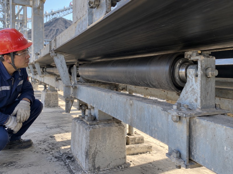
What should you inspect below the conveyor?
Review return contact and cleaning access together. Carryback can alter roller surfaces and restrict movement. Material may also collect around a pivot or mounting bracket. Check return support arrangements and nearby structure before approving placement.
- Verify belt profile and approved support arrangement.
- Inspect clearance for pivot travel and belt movement.
- Identify deposits, cleaners and material collection paths.
If contamination repeatedly changes contact, correct its source. A new tracker cannot replace cleaning provisions or resolve every return-side fault. Include recurring exposure in your supplier inquiry and maintenance plan.
Which return condition requires attention?
| Condition | Effect on installation | Review |
|---|---|---|
| Carryback deposits | Changes contact or movement | Cleaning and access |
| Restricted underside space | Limits assembly travel | Clearance envelope |
| Unsuitable support profile | Alters engagement | Approved return-duty design |
Key Takeaway: Specify return duty explicitly. Review contamination and movement space before adopting a carrying-side arrangement.
6. Which mounting interfaces need inspection?
Inspect shaft ends, fixing features, bracket attachments and installed alignment against approved dimensions. A self aligning idler needs secure mounting without distortion. If your replacement requires frame alteration, get design approval before modifying structural interfaces.
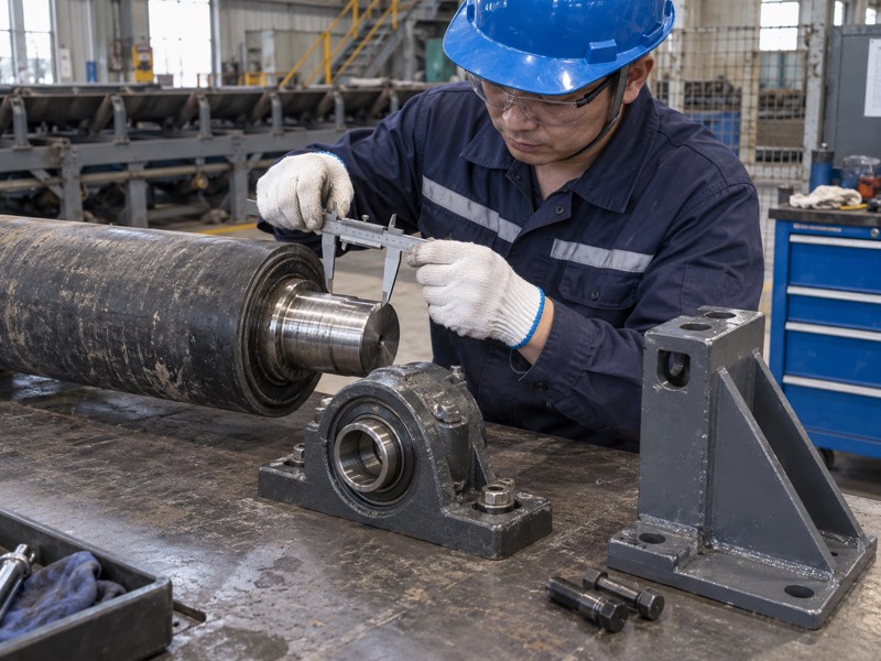
How do you prevent fit assumptions?
Check the installed assembly from defined datums. Overall appearance cannot establish shaft fit or bracket position. Verify end details and the mounting method. Then check whether fastening changes movement or contact.
- Record shaft-end geometry and mounting-center dimensions.
- Confirm bracket alignment and fastening requirements.
- Check clearances after all specified parts are fitted.
If a supplier proposes different bearings, shafts or brackets, ask for a revised drawing. Substitutions may change fit even when working-face dimensions match. Keep approved deviations with your installation record.
What does each interface control?
| Interface | Controlled relationship | Inspection |
|---|---|---|
| Shaft end | Retention and fit | Dimensioned detail |
| Bracket attachment | Installed position | Mounting reference |
| Frame connection | Alignment and movement | Complete assembly check |
Key Takeaway: Approve interfaces before installation. Preserve supplier deviations and final mounting measurements for future replacement orders.
7. How should you inspect pivot travel?
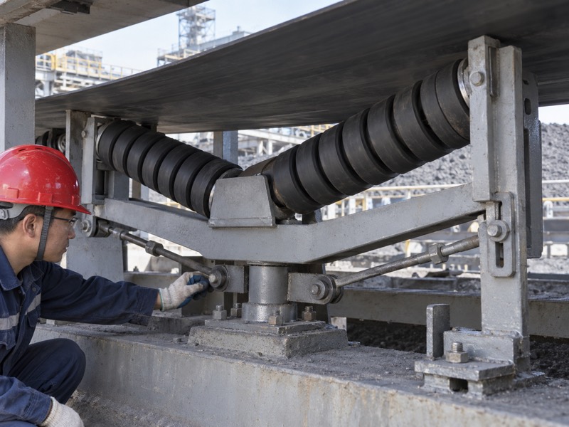
Inspect pivot travel through its permitted range after isolation, following the assembly’s procedure. Your self aligning idler needs free designed movement. Binding, looseness or structural interference can prevent an otherwise sound roller from providing its intended response.
What should a movement check cover?
Check both freedom and limits of travel. A mechanism should move as its design permits while stops remain effective. Deposits or damaged interfaces may restrict movement. Excess wear can also leave response uncertain even when a frame moves easily.
- Inspect pivots, bushes, bearings and links where fitted.
- Confirm stops and surrounding clearances.
- Record binding, play or contact with fixed structure.
Don’t remove stops or alter links to gain movement. If travel does not match instructions, investigate mounting and damage. Ask for technical clarification before changing the mechanism.
Which finding supports which repair?
| Finding | Possible cause | Action |
|---|---|---|
| Restricted movement | Deposits or damaged pivot | Restore approved travel |
| Excessive play | Worn interface | Repair specified parts |
| Unexpected stop contact | Incorrect mounting geometry | Check installation drawing |
Key Takeaway: Inspect controlled movement rather than freedom alone. Keep travel limits intact while correcting binding or wear.
8. How do you check sensing contact and belt edges?
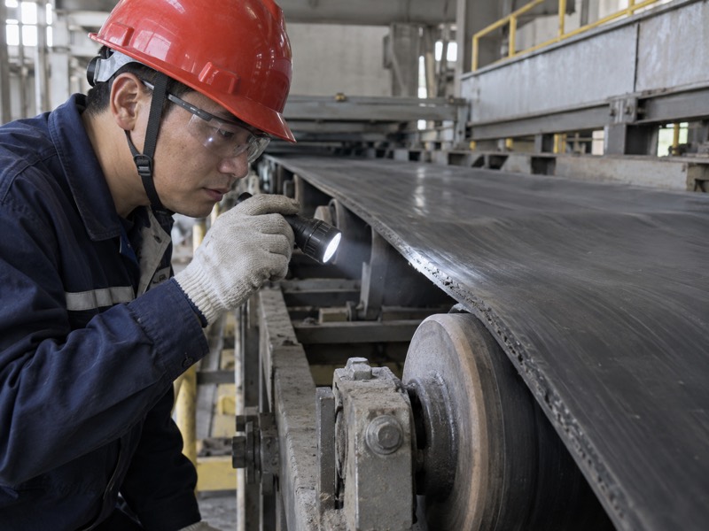
Check sensing positions, edge clearance and contact height against model-specific instructions. A self aligning idler with edge-sensing parts needs suitable contact without unacceptable wear. If an edge rubs constantly, investigate drift and installation before narrowing clearance.
What contact signs should you record?
Compare edge marks with the sensing location. A seized sensor roller can create sliding friction. Incorrect height can fold or climb an edge. Inspect guide roller contact along with supporting links and brackets.
- Check sensing roller rotation after isolation.
- Inspect edges for cuts, polish or exposed reinforcement.
- Verify contact location and surrounding bracket clearance.
If belt construction or width has changed, review its compatibility with existing settings. An earlier clearance may no longer suit operating geometry. Keep belt details with your assembly adjustment record.
What does each contact sign suggest?
| Sign | Possible concern | Check |
|---|---|---|
| Constant edge rubbing | Persistent drift or tight setting | Baseline and clearance |
| Edge folds near contact | Unsuitable contact height | Installation geometry |
| Sensor fails to rotate | Sliding rather than rolling contact | Bearing and seal condition |
Key Takeaway: Check sensing contact against approved limits. Investigate edge damage before treating repeated contact as normal operation.
9. How should you commission the installed assembly?
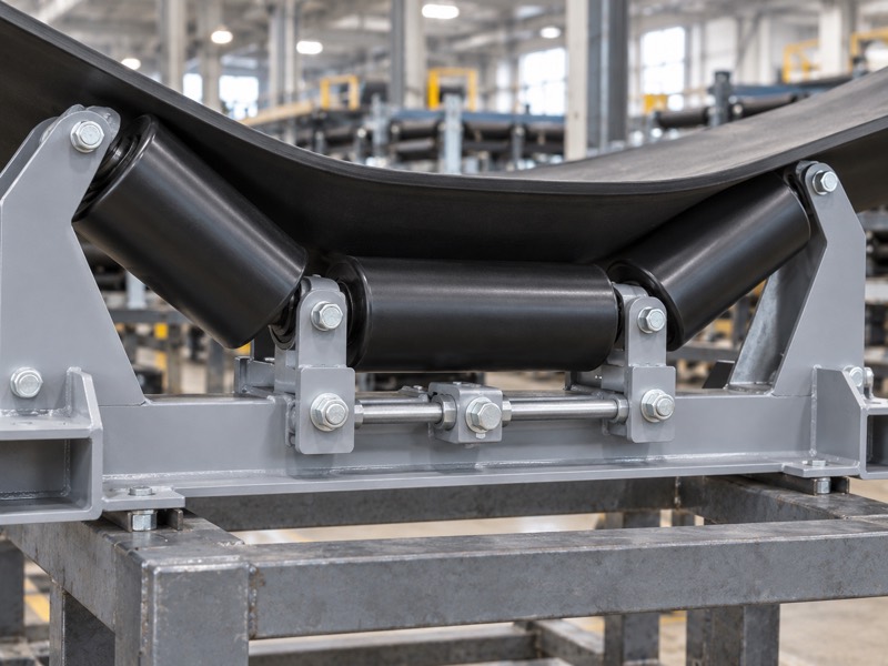
Commission it through controlled trials after confirming mounting, movement, contact and guards. Your self aligning idler needs review under relevant operating conditions. If loaded behavior differs from empty running, use that evidence before changing another setting.
What trial sequence should you record?
Change one approved setting at a time. Keep a record of initial position and belt behavior. Observe from designated safe locations. Then compare relevant operating conditions against acceptance criteria agreed before installation.
- Confirm fastening, travel limits and guarding before restart.
- Observe empty and representative loaded operation.
- Record belt path, contact and assembly response.
If your conveyor reverses, trial both directions only when the assembly has approved reversing duty. Normal stops and starts may also change behavior. Include those conditions where your commissioning plan requires them.
Which result belongs in acceptance records?
| Trial area | Evidence | Acceptance reference |
|---|---|---|
| Installed geometry | Dimensions and movement | Approved drawing |
| Empty running | Initial path and contact | Operating envelope |
| Loaded duty | Response under relevant load | Agreed trial criteria |
Key Takeaway: Accept the assembly under specified conditions. Keep adjustment and observation records so later drift has a useful baseline.
10. What should you hand over to maintenance?
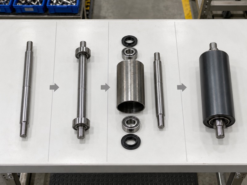
Hand over final drawings, settings, trial results and inspection requirements. A self aligning idler needs ongoing checks on rotation, contact and movement. If your records omit the installed configuration, future repairs may repeat incompatible settings or parts.
How do you make future checks practical?
Record what technicians should inspect and compare. Include part identity, location and approved movement limits. State maintenance provisions supplied for bearings and pivots. Then define how findings should trigger repair through your site procedure.
- Keep drawings and accepted supplier deviations together.
- Record contact settings and belt construction.
- Preserve trial observations and relevant wear photographs.
Inspection intervals should follow duty and site planning. Avoid promising a universal replacement schedule. Review recurring faults so mounting, contamination or belt changes do not remain hidden behind repeated component replacement.
Which handover record supports which task?
| Record | Maintenance task | Benefit |
|---|---|---|
| Final drawing | Match replacement interfaces | Correct fit |
| Approved settings | Restore known configuration | Consistent contact |
| Trial and wear baseline | Compare changing behavior | Evidence for repair |
Key Takeaway: Close installation with a usable maintenance record. Keep approved settings and component drawings available where future work is planned.
FAQ
Q1: Can I place an aligning idler anywhere? No. Contact, approach geometry, structure and clearance need an approved placement review.
Q2: How do I know whether a pivot needs repair? Inspect permitted movement after isolation. Record binding, excessive play or interference.
Q3: Can one assembly suit carrying and return duty? Only if approved for both. Their belt profiles and contact conditions can differ.
Q4: What’s the best commissioning evidence? Keep mounting checks and representative operating records. Include empty and loaded behavior where relevant.
Q5: Should I remove travel stops to improve correction? No. Stops belong to the designed mechanism and its permitted movement.
Send your installation drawing and belt-duty details when you contact us about self-aligning idler requirements.