
A friction roller used in belt tracking transfers contact forces within a designed aligning assembly. Its role differs from a powered roller driving packages. If your belt drifts despite a new component, inspect contact, pivot movement and upstream conditions. A complete assembly review gives you a sound basis for choosing replacements.
1. What does a friction roller do in belt tracking?
A friction roller contributes to corrective action through belt contact within its specified assembly. The surrounding mechanism determines how those forces influence belt direction. If you order a roller without identifying that mechanism, you can miss parts required for its intended function.
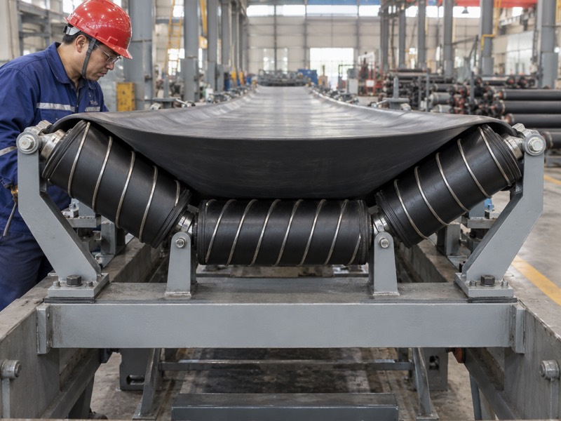
Which duty does your product name describe?
State whether you need tracking or powered conveying. Friction can transfer force in several machine arrangements. A powered roller uses a drive input for conveying loads. A tracking component works within a guiding assembly, so its quotation requires different application details.
- Identify what contacts your roller during operation.
- State whether any motor or transmission drives rotation.
- Show the complete frame and corrective mechanism.
Then ask how a proposed component fits your installed arrangement. Similar product names do not establish equivalent contact geometry or function. Keep a marked drawing with your inquiry so technical reviewers can identify the correct duty.
How should you describe the requirement?
| Duty | Main function | Information needed |
|---|---|---|
| Belt-tracking component | Works within an aligning assembly | Complete mechanism |
| Powered conveying roller | Receives drive motion | Transmission details |
| Replacement spare | Matches existing approved duty | Drawing and part location |
Key Takeaway: Define roller duty before comparing quotations. Use an assembly drawing to separate tracking components from powered-drive products.
2. How does friction create corrective movement?
Friction transfers force through contact, and a designed mechanism uses that force to influence support orientation or belt travel. A friction roller alone does not define the complete response. Your assembly needs suitable contact and free movement within approved limits.
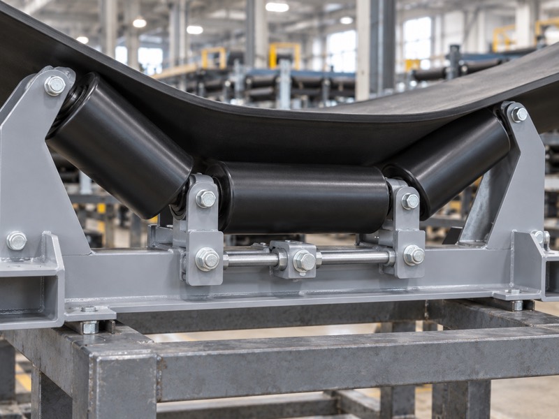
What should a mechanism drawing explain?
Trace force from contact through the assembly. Identify the contacting surface, pivot and any sensing or linkage parts. Then find mechanical stops and mounting references. If the supplier cannot explain those relationships, corrective behavior remains too unclear for purchasing approval.
- Identify which component moves when belt position changes.
- Confirm how pivot travel or sensing contact is limited.
- Check clearance around all permitted movement.
Because belt behavior depends on approach and loading, a mechanism’s response can vary with operating conditions. Don’t substitute a universal correction promise for application review. Ask for suitable duty and installation instructions tied to the actual model.
Which feature supports which function?
| Feature | Mechanical role | Verification |
|---|---|---|
| Contact surface | Transfers belt force | Approved engagement |
| Pivot or linkage | Produces designed movement | Free permitted travel |
| Stops and frame | Limit and support movement | Complete assembly drawing |
Key Takeaway: Request an explanation of force and movement. Approve contact, pivot travel and limits as one installation requirement.
3. Which conveyor faults should you repair beforehand?
Repair known loading, alignment, buildup and rotating-support faults before evaluating a friction roller. Such faults can impose persistent drift beyond a device’s intended role. If they remain unresolved, changing surface grip may conceal symptoms while wear continues.

How do you build a useful fault record?
Document when and where drift begins. Compare relevant empty and loaded behavior from safe observation points. Record whether a disturbance follows a splice or remains near one frame. Then inspect likely causes after approved isolation.
- Check feed position and material distribution across the belt.
- Inspect frame alignment and roller rotation.
- Record deposits and damage along carrying and return paths.
Your carrying roller support affects how the belt enters a tracking assembly. Unequal support or a seized roller can change approach conditions. Correct documented faults before trialing a new aligning component.
What does each pattern suggest?
| Pattern | Candidate source | Review |
|---|---|---|
| Loaded drift | Uneven feed | Chute and support |
| Local persistent drift | Skewed or seized support | Frame and roller condition |
| Repeated belt-position event | Splice or belt damage | Identified belt area |
Key Takeaway: Give tracking hardware a sound conveyor baseline. Keep fault and repair records so trial results have a clear reference.
4. How does surface contamination change contact?
Deposits can change friction, contact geometry and roller rotation. A friction roller exposed to dust, moisture or sticky material needs a suitable surface and maintenance plan. If contamination recurs, inspect its source instead of relying only on frequent cleaning.
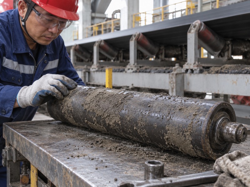
Which contamination details should you provide?
Describe what reaches the contact surface. Wet fines behave differently from dry dust or sticky carryback. Material can collect unevenly and change local contact. Cleaning chemistry may also affect surfaces or seals, so include it in your duty description.
- Identify material type and likely contamination paths.
- Record cleaning methods and chemical exposure.
- Photograph recurring deposits before their removal.
Surface selection requires application confirmation. More grip does not guarantee better correction under every condition. If uneven deposits alter contact, resolve cleaning and support issues before selecting another surface treatment.
Which exposure calls for which review?
| Exposure | Potential effect | Selection question |
|---|---|---|
| Wet fines | Changes surface contact | Suitable surface proposal |
| Sticky deposits | Alters effective geometry | Cleaning and buildup control |
| Cleaning chemicals | Affects material compatibility | Approved cleaning limits |
Key Takeaway: Specify contamination and cleaning duty. Ask suppliers to explain suitability rather than promising a universal grip level.
5. What bearing and seal checks should you make?
Check rotating resistance, abnormal movement and seal condition against your approved inspection method. A friction roller with damaged bearings can drag against belt contact. If rotation changes, inspect contamination and mounting before treating surface wear as the only fault.
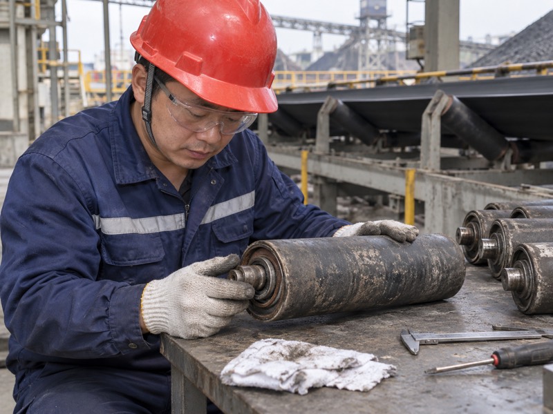
What makes a rotation check useful?
Pair hand-rotation observations with installed evidence. Unloaded movement on a bench cannot prove acceptable behavior under belt contact. Record roughness, looseness and visible seal damage. Then compare findings with wear marks and operating exposure.
- Confirm shaft arrangement and permitted inspection steps.
- Check bearings and seals for documented damage signs.
- Record mounting security and roller surface condition.
Use site-approved hazardous-energy control before physical conveyor inspection. If a bearing has no lubrication provision, don’t add grease through an improvised opening. Follow its maintenance instructions and replace unserviceable components.
Which evidence helps a repair decision?
| Evidence | Possible issue | Additional check |
|---|---|---|
| Rough rotation | Bearing or seal damage | Contamination exposure |
| Excessive movement | Worn or loose interface | Shaft and mounting |
| Sliding marks | Roller fails to turn properly | Rotation under approved test |
Key Takeaway: Inspect bearings, seals and mounting together. Use records that distinguish rotating-component failure from unsuitable contact geometry.
6. Why must pivot movement stay free?
Free pivot movement allows a tracking assembly to respond through its intended mechanism. A friction roller cannot provide designed correction if the supporting frame binds. If movement feels restricted during inspection, identify its cause before adjusting belt contact.
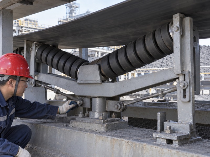
What can interfere with travel?
Inspect the full movement envelope. Deposits, corrosion and damaged interfaces can restrict travel. Nearby guards or misplaced brackets may also obstruct movement. Check through the permitted range after isolation, using your approved assembly procedure.
- Examine pivot bearings or bushes for wear and binding.
- Verify clearance around links and moving frames.
- Confirm stops remain installed in their specified positions.
Then review mounting distortion or loose fasteners that change geometry. Don’t remove a stop to gain extra movement. Your mechanism needs its approved travel limits for predictable operation and structural compatibility.
Which pivot finding needs which response?
| Finding | Effect | Response |
|---|---|---|
| Deposits restrict movement | Response becomes limited | Clean through approved method |
| Worn pivot interface | Geometry becomes uncertain | Repair defined interface |
| Guard interference | Movement stops unexpectedly | Correct installation clearance |
Key Takeaway: Include pivot checks in every tracking inspection. Preserve travel limits while restoring free movement.
7. Which installation dimensions influence performance?
Support elevation, mounting alignment and contact locations affect how a friction roller works within its assembly. You should verify these against approved drawings. If a replacement changes diameter or bracket position, its installed contact can also change.
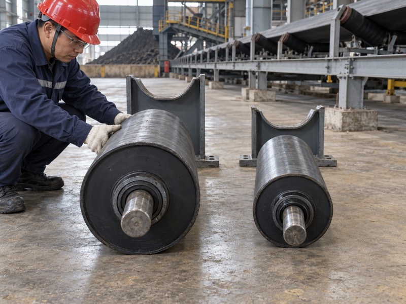
What should your mounting drawing show?
Measure position from a defined conveyor reference. Record shaft interfaces, bracket attachments and adjacent support. Include clearances for expected belt movement and assembly travel. Photos help explain orientation, but measured references establish fit.
- Show mounting centers and shaft-end details.
- Define roller elevation and orientation.
- Identify neighboring frames and required clearance.
If your conveyor uses different carrying and return support, identify which duty applies. Their belt profiles and loading conditions differ. Require written approval when a proposed replacement departs from installed geometry.
Which dimension affects which relationship?
| Dimension | Relationship | Approval evidence |
|---|---|---|
| Support elevation | Belt engagement | Installation drawing |
| Shaft and bracket geometry | Secure fit | Interface detail |
| Movement clearance | Available corrective travel | Assembly envelope |
Key Takeaway: Specify installed geometry as well as roller dimensions. Confirm application and mounting before treating a spare as interchangeable.
8. How should you interpret contact-surface wear?
Interpret wear alongside contact location, roller rotation and belt behavior. A friction roller can show uneven damage from geometry, deposits or failed movement. If you change material without identifying those conditions, the same wear pattern may return.
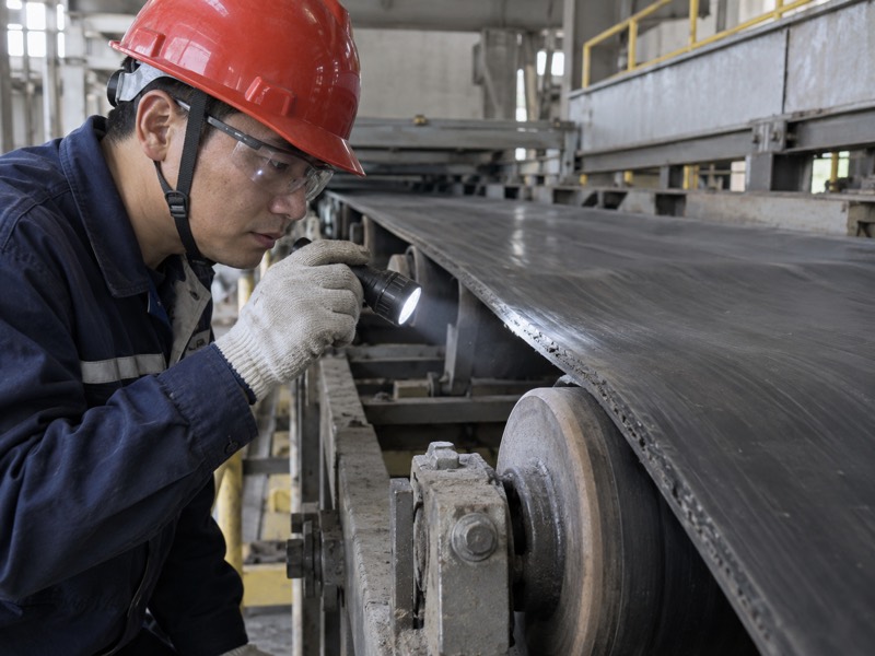
What does a wear record need?
Preserve evidence before cleaning or scrapping parts. Photograph the working face and mark installed orientation in your maintenance record. Compare belt marks with roller damage. Then inspect whether contact was concentrated at one end or affected across the face.
- Record wear location and visible surface condition.
- Note belt drift and loading when damage appeared.
- Inspect bearings, pivot and mounting with the removed component.
Wear cannot establish service life from one observation. Duty and exposure affect future behavior. Use your records to define inspection actions and supplier questions rather than inventing a replacement interval.
Which pattern points toward which check?
| Wear pattern | Possible relationship | Inspection focus |
|---|---|---|
| Localized contact band | Uneven engagement | Installed geometry |
| Deposits beside wear | Changed contact surface | Cleaning source |
| Damage with poor rotation | Sliding contact | Bearings and seals |
Key Takeaway: Use wear as evidence of installed conditions. Retain its location and operating context before selecting another surface construction.
9. What information should your quotation include?
Include the complete assembly, operating duty, mounting interfaces and acceptance requirements when requesting a friction roller. A named product alone cannot establish application fit. If you need only a component, define exactly which parts remain in service.
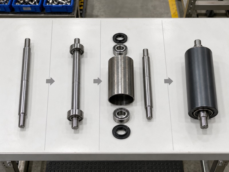
How do you keep proposals comparable?
Define the same scope for each quotation. State whether frames, pivots, brackets and sensing parts are included. Give drawing revisions and known operating conditions. Then ask suppliers to identify deviations and unresolved application questions.
- Provide belt construction, dimensions, speed and directions.
- Describe contamination, temperature and cleaning exposure.
- Define inspection methods and required supporting records.
Avoid replacing measurable requirements with broad quality terms. Fit, rotation and interface checks should use agreed references. Operational tracking acceptance should also state conditions under which you will trial the assembly.
Which quotation field prevents ambiguity?
| Field | Decision supported | Required response |
|---|---|---|
| Supply scope | What arrives with the roller? | Itemized component list |
| Controlled drawing | Will interfaces match? | Revision and deviations |
| Duty and acceptance | What conditions apply? | Written suitability and tests |
Key Takeaway: Quote a defined scope against a controlled drawing. Keep unresolved fit or duty questions visible until technical approval.
10. How should you commission a replacement?
Commission it after restoring known conveyor faults and verifying approved mounting, contact and movement. Your friction roller needs representative operating checks within its assembly. If drift remains, use recorded evidence before making further adjustments.
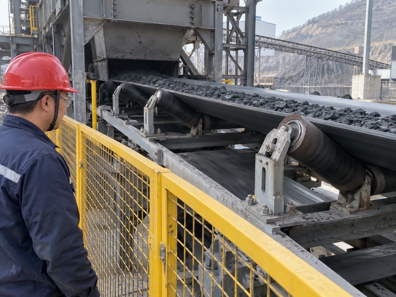
What should your trial record contain?
Keep each approved change traceable. Record the initial configuration and belt path before starting. Observe relevant empty and loaded operation from safe locations. Then note whether contact, pivot response and belt movement meet agreed criteria.
- Confirm guards, mounting and travel limits before operation.
- Record belt position and contact behavior during trials.
- Review any recurring drift against your fault baseline.
Change one approved setting at a time after required isolation. If correction becomes erratic, stop and inspect conditions rather than increasing contact force repeatedly. Keep final results with drawings and installed part identity.
Which result supports release?
| Trial check | Evidence | Decision |
|---|---|---|
| Assembly installation | Approved geometry and limits | Ready for trial |
| Representative operation | Contact and belt-path record | Meets agreed criteria |
| Unresolved drift | Repeatable fault evidence | Further cause review |
Key Takeaway: Accept a replacement through documented assembly behavior. Preserve baseline and final results for maintenance and future purchasing.
FAQ
Q1: Can a friction roller power my conveyor? Only if designed for powered duty. Tracking components have a different role and assembly.
Q2: Will more grip always improve tracking? No. Contact geometry, contamination and free movement also control response.
Q3: How do I know whether the pivot has failed? Inspect permitted movement after isolation. Record binding, wear or interference against assembly instructions.
Q4: Can I change roller diameter for better contact? Only with design approval. Diameter changes installed engagement and surrounding clearances.
Q5: What’s the best evidence for replacement selection? Use drawings, duty details and a fault record. Include contact and wear observations.
Send your assembly drawing and operating record when you contact us about friction-roller selection.