
Conveyor roller types should be selected by support function, belt contact and operating conditions. A replacement that fits a bracket may still be unsuitable for loading impact, wet carryback or tracking duty. Compare conveyor roller types using a conveyor position map and approved drawings. Bulk belt-conveyor idlers support a moving belt; exposed package rollers perform a different transport function.
1. How should conveyor roller types be classified?
Classify conveyor roller types by where they work and what they must do. Carrying, return, impact and guidance functions describe different duties. Material names and surface shapes add another layer of specification rather than replacing those functions.
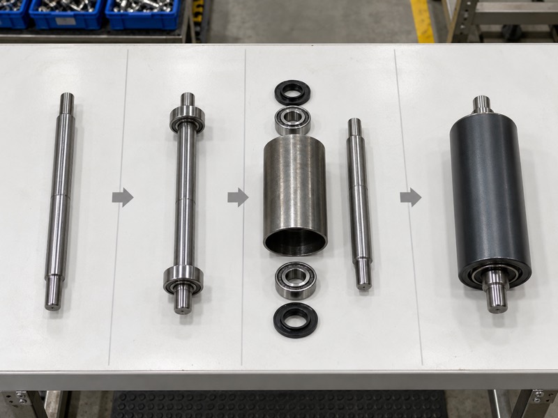
Separate function from construction
Begin with the installation position. A steel shell, polymer shell, rubber discs or helical elements can change contact behavior. However, the assembly still needs an approved load, shaft fit and bearing arrangement. Identify which features solve your operating problem before choosing a product label.
- Mark carrying, loading, return and guidance positions.
- Record belt width, speed and support spacing.
- Describe abrasion, moisture and deposit conditions.
Keep package transport separate
Package conveyors carry cartons or pallets directly on exposed rollers. Bulk belt conveyors use rollers beneath a belt, so package spacing and drive selection do not transfer automatically. Confirm which system your drawing represents before applying a roller-design recommendation.
| Classification | Describes | Required next detail |
|---|---|---|
| Function | Support duty | Position and load |
| Surface geometry | Belt contact | Compatibility |
| Material | Construction choice | Grade and limits |
Use all three categories when preparing specifications. Key Takeaway: Identify function before selecting surface geometry or material.
2. When should you use carrying rollers?
Use carrying rollers where approved assemblies support a loaded belt under defined spacing and loading. Among conveyor roller types, they form the carrying-run support arrangement. Flat or troughed configurations depend on your conveyor layout and material-handling requirements.
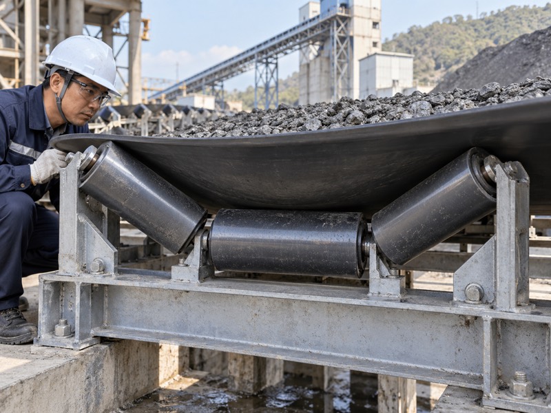
Review loaded-belt support
Match support with the actual load path. Belt mass, conveyed material and uneven feed affect loading. Roller length and frame arrangement also influence contact. A replacement should preserve approved trough geometry and mounting height unless your conveyor designer authorizes a change.
- Provide loaded duty, belt width and speed.
- Confirm roller spacing and trough arrangement.
- Inspect shaft seats and frame alignment.
Identify conditions beyond ordinary carrying duty
For example, a loading zone with falling material needs an impact review even if its frame resembles another carrying station. Long spans or concentrated loads also deserve specific checks. A carrying designation alone does not define capacity for every operating event.
| Carrying condition | Review focus | Required confirmation |
|---|---|---|
| Normal loaded support | Load and spacing | Assembly rating |
| Uneven feed | Contact distribution | Layout review |
| Changed trough geometry | Belt behavior | Engineering approval |
Compare replacements against a complete carrying arrangement. Key Takeaway: Preserve approved load support, trough geometry and mounting interfaces.
3. How do return rollers differ from carrying rollers?
Return rollers support a belt traveling back after discharge, so their duty differs from loaded carrying support. Conveyor roller types should distinguish return positions explicitly because duty differs. Belt mass, tension, spacing and carryback still influence return assembly requirements.
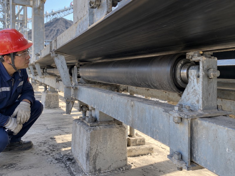
Check contamination as well as support
Inspect the returning contact surface. Carryback can form deposits on roller surfaces or accumulate around end housings. Plain return rollers remain a useful baseline where those conditions are manageable. Special surfaces deserve review when repeated deposits change support geometry or cleaning workload.
- Identify which belt face contacts each assembly.
- Record existing return spacing and clearances.
- Describe deposits and upstream cleaner condition.
Review replacement geometry
If effective outside diameter changes, belt contact height may also change. Confirm bracket fit and useful support length rather than relying on nominal belt width. Return duty can vary around pulleys and other constrained locations, so approve each intended position.
| Return concern | Component review | Related system check |
|---|---|---|
| Belt support | Length and spacing | Return layout |
| Carryback | Working surface | Cleaner condition |
| End contamination | Bearings and seals | Deposit discharge |
Use support and contamination findings together when selecting return assemblies. Key Takeaway: Choose return rollers for actual support and carryback conditions rather than carrying-run assumptions.
4. When do impact rollers belong at loading points?
Impact rollers belong where approved resilient support helps manage falling-material loading on a belt. Within conveyor roller types, impact construction addresses a specific loading-zone condition. Material drop, lump characteristics and belt support determine suitability.
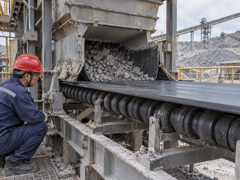
Describe impact before choosing construction
Give the supplier a loading description. Drop height, material flow and large-particle characteristics influence impact exposure. Rubber elements do not establish unlimited shock capacity. Ask your engineer to review the complete loading arrangement, including chute geometry and support spacing.
- Identify loading position and material entry direction.
- Describe falling lumps and normal operating flow.
- Check belt contact and surrounding clearance.
Inspect resilient elements during service
Impact rollers need inspection for damaged elements, uneven contact and end condition. If loading moves off-center, investigate transfer geometry rather than assuming stronger rollers alone will solve it. Keep carrying and impact specifications distinct in your purchase package.
| Loading issue | Review | Component consequence |
|---|---|---|
| Falling material | Impact conditions | Approved resilient support |
| Off-center entry | Chute and feed | Uneven contact investigation |
| Worn elements | Surface inspection | Replacement review |
Approve support alongside transfer conditions before ordering replacements. Key Takeaway: Select impact construction from defined loading conditions and inspect its working elements regularly.
5. Can guide rollers correct every tracking problem?
Guide rollers cannot correct every tracking problem, because loading, alignment and belt defects can also cause drift. Conveyor roller types used for guidance need compatible contact and approved positioning. Constant heavy edge pressure deserves investigation.
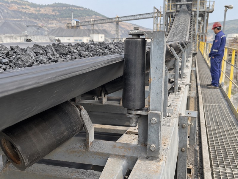
Investigate drift before adding contact
Find the pattern of deviation. Compare safely observed behavior under relevant operating conditions, then isolate equipment for mechanical checks. Inspect skewed frames, buildup, pulley alignment and splice condition. Guidance should complement an approved layout rather than conceal unresolved damage or loading problems.
- Record whether drift changes with conveyed load.
- Inspect belt edges for abrasion or repeated contact.
- Check guide clearance and mounting condition.
Keep adjustments within approved procedures
During contact inspections, follow site-approved lockout/tagout procedures and control stored energy. Increasing guide pressure without a design basis can worsen edge wear. Ask a conveyor specialist to approve modifications involving belt guidance or tracking assemblies.
| Tracking observation | Investigation | Avoid assuming |
|---|---|---|
| Load-dependent drift | Feed placement | Guide pressure solves it |
| Constant edge contact | Alignment and clearance | Contact is harmless |
| Deposit-related variation | Clean surfaces | Guidance replaces cleaning |
Review guidance after establishing a sound mechanical baseline. Key Takeaway: Investigate tracking causes before adding or adjusting guide contact.
6. Where do taper rollers fit a belt conveyor?
Taper rollers fit belt-conveyor arrangements that have been designed for their changing diameter and contact geometry. Their place among conveyor roller types depends on the actual assembly. Taper geometry alone does not establish a universal steering function.
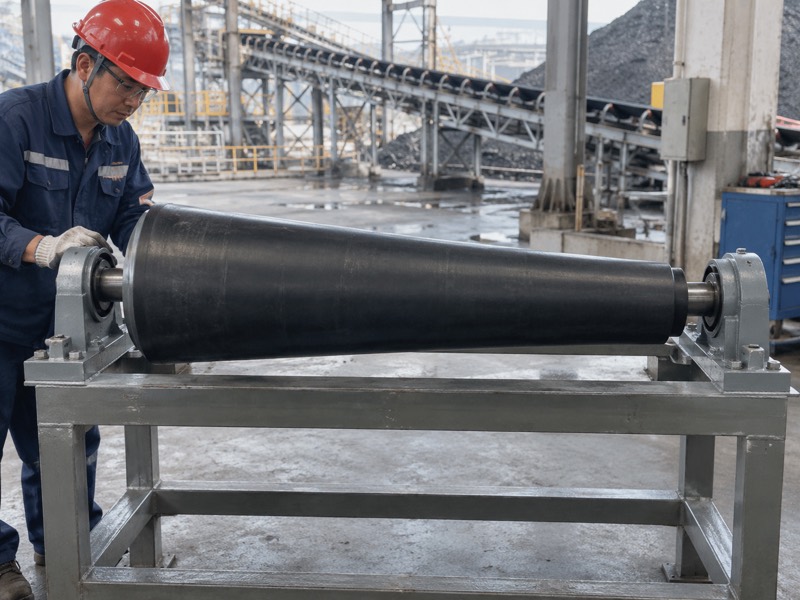
Confirm the intended assembly
Ask which contact geometry the drawing requires. A taper changes local diameter along a roller’s length, so orientation and support arrangement matter. Some guidance or training constructions use particular geometries. Their behavior must be reviewed as a complete assembly rather than inferred from an isolated product photograph.
- Identify large and small ends on a drawing.
- Confirm intended mounting orientation and belt contact.
- Check shaft interfaces and adjacent clearances.
Distinguish package-conveyor curves
For example, tapered exposed rollers on a package conveyor serve a different transport arrangement. Those recommendations cannot automatically specify a belt-support component. State your machine type and drawing requirements when requesting taper construction.
| Taper question | Information needed | Decision supported |
|---|---|---|
| Orientation | Approved drawing | Correct mounting |
| Belt contact | Assembly geometry | Compatibility |
| Machine function | Belt or exposed rollers | Relevant specification |
Approve taper dimensions through the intended conveyor arrangement. Key Takeaway: Select taper rollers from an assembly drawing that defines orientation and contact duty.
7. What should you check about friction rollers?
Check friction rollers for their intended contact function, assembly geometry and approved operating conditions. Among conveyor roller types, a friction label needs clarification because different machines use friction differently. An idler product should not be assumed to provide powered package transport.
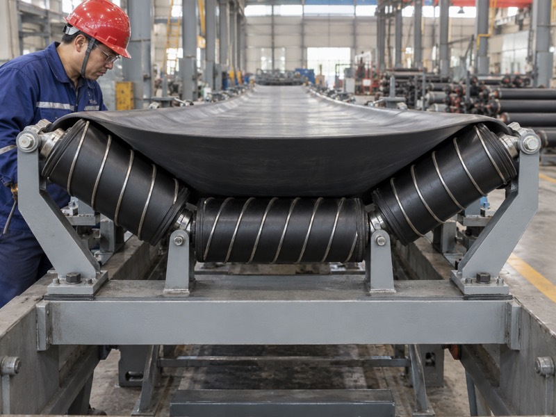
Identify what friction is meant to do
Request the assembly description. Belt contact, training mechanisms and drive arrangements impose different requirements. Ask whether your proposed roller belongs within a particular belt-guidance construction. Any claimed tracking effect should be linked with approved mounting and operating conditions.
- Describe the intended conveyor function clearly.
- Request surface construction and contact requirements.
- Confirm whether associated frames or mechanisms are needed.
Inspect contact and wear together
If friction surfaces wear unevenly, contact behavior may change. Record deposits, surface condition and belt marks during inspections. Avoid changing a contact material or roller diameter independently when its function depends on a larger mechanism.
| Friction requirement | Needed detail | Approval question |
|---|---|---|
| Belt contact | Surface construction | Suitable for this belt? |
| Training assembly | Mounting geometry | Complete mechanism defined? |
| Replacement | Dimensions and wear | Equivalent working contact? |
Keep friction function explicit in drawings and quotations. Key Takeaway: Clarify intended friction duty before selecting or replacing the roller.
8. How do comb and spiral rollers address carryback?
Comb and spiral rollers address carryback through different return-contact geometries. These conveyor roller types may change how deposits accumulate or detach, but neither replaces upstream cleaning automatically. Material behavior and belt compatibility determine whether either geometry helps.
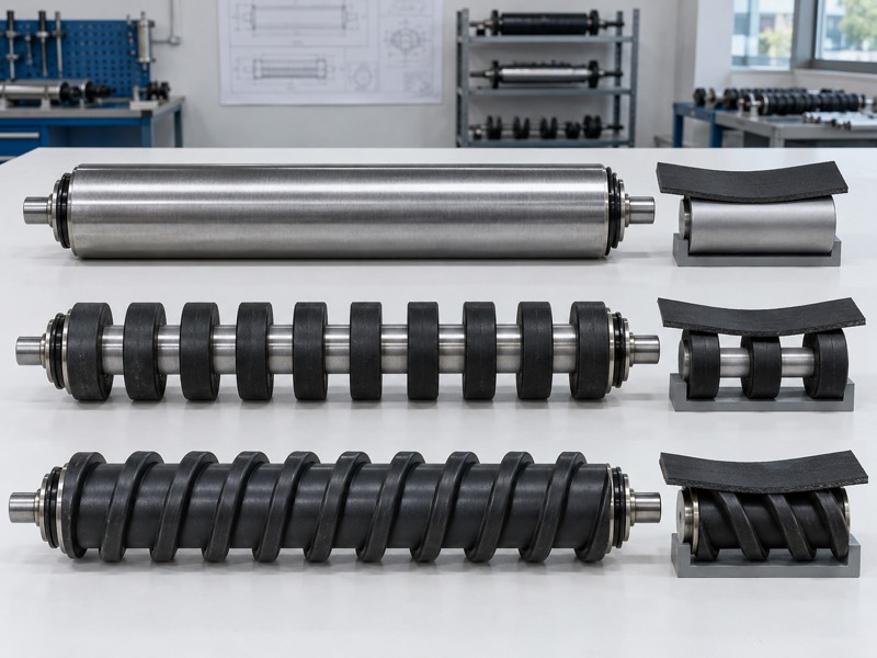
Compare contact patterns
Watch what collects between elements. Separated discs leave gaps that may permit deposits to fall away, while helical elements change contact across a working face. However, adhesive material can still bridge spaces or accumulate. Inspect actual constructions instead of assuming a general self-cleaning promise applies.
- Record deposit moisture, adhesion and distribution.
- Check element condition and belt-cover marks.
- Confirm support length, diameter and mounting fit.
Trial one defined problem
Comb rollers and spiral surfaces should be compared at relevant return positions. Record cleaning effort, deposit behavior and component wear under similar operating conditions. A short trial can confirm initial suitability while leaving seasonal or longer-term behavior unresolved.
| Surface | Inspection focus | Trial question |
|---|---|---|
| Separated discs | Gap bridging | Does deposit accumulation change? |
| Helical elements | Wear and residue | Is belt contact suitable? |
| Plain surface | Continuous deposits | Is special geometry needed? |
Choose a surface from observed service behavior and mechanical fit. Key Takeaway: Evaluate comb and spiral support through a defined carryback trial.
9. How do UHMW rollers change material selection?
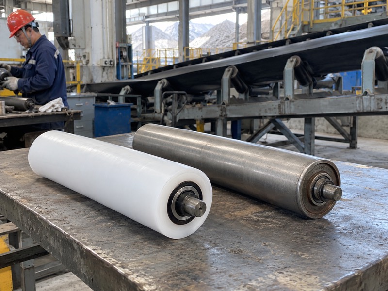
UHMW rollers change working-surface material, while function and assembly requirements still govern selection. Compare conveyor roller types using exact polymer grade and complete construction. Material labels alone cannot establish load, temperature or electrical suitability.
Review a complete polymer assembly
Separate shell properties from roller performance. Shaft stiffness, bearing arrangement, sealing and end attachment influence service behavior. A polymer working surface may suit some corrosion or deposit conditions, but exposed metal components still need review. Ask for temperature limits and relevant chemical compatibility information.
- Identify exact shell grade and construction.
- Confirm load basis and dimensional stability requirements.
- Request electrical evidence where site requirements apply.
Compare benefits using measurements
For example, complete assembly mass can support a handling comparison. It cannot establish an energy-saving percentage or lifetime ratio. Use local trial records for deposits, wear and maintenance before extending polymer construction across other conveyor positions.
| Material question | Evidence needed | Avoid assuming |
|---|---|---|
| Load and heat | Assembly-specific limits | Steel rating transfers |
| Chemical exposure | Relevant compatibility | Every component resists it |
| Electrical behavior | Product-specific evidence | Ordinary polymer is antistatic |
Approve material selection within a defined mechanical and environmental duty. Key Takeaway: Treat UHMW as a construction option requiring complete assembly review.
10. What should a conveyor roller types inquiry include?
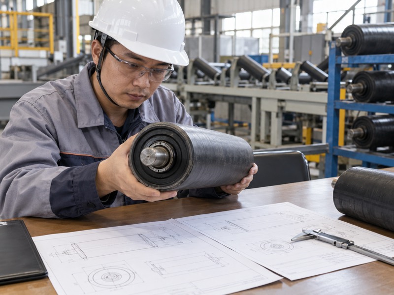
A conveyor roller types inquiry should include a position map, approved drawings and operating conditions for each required function. One general roller label cannot describe every conveyor location. Separate quantities and acceptance requirements by assembly type.
Build a useful component schedule
Give each position a clear specification. List carrying, return, impact and any special-contact assemblies separately. Include belt width, speed, spacing and contamination exposure. Ask suppliers to identify construction differences and proposed substitutions before you compare prices.
- Provide shaft-end geometry and required dimensions.
- Explain existing failures or intended operating problems.
- State sample approval and inspection expectations.
Confirm scope before purchasing
| Inquiry item | Supplier response | Buyer decision |
|---|---|---|
| Function and position | Proposed assembly | Appropriate duty |
| Approved drawing | Dimensions and deviations | Installation fit |
| Exposure and belt | Construction recommendation | Compatibility review |
Key Takeaway: Request a position-specific quotation rather than one universal conveyor roller proposal. Send XINYONGDUO your roller schedule, drawings, belt dimensions and operating conditions. Contact us for a quotation covering confirmed carrying, return and special-support requirements. Your maintenance team should receive clearly identified assemblies that match approved conveyor positions.
FAQ
Q1: Can I interchange carrying and return rollers? Only after approval. Compare loading, support geometry, shafts, bearings and contact requirements for each position.
Q2: What’s the best roller for a loading zone? Use an approved loading-support design based on material impact and belt conditions. A generic carrying roller may not meet those demands.
Q3: How do I know if a guide roller needs adjustment? Inspect clearance, edge marks and tracking behavior. Investigate underlying alignment or loading issues before changing contact pressure.
Q4: Can polymer rollers automatically replace steel? No. Check complete construction, temperature, load, shaft fit and applicable electrical requirements before substitution.
Q5: Are belt idlers and package-conveyor rollers identical? No. Belt idlers support a moving belt, while exposed package rollers directly support goods and may involve separate drive requirements.