
conveyor belt tracking rollers can help guide a belt when their complete assembly suits your conveyor. You still need to find why drift starts. If you add a trainer beside a damaged edge without checking loading or alignment, persistent side force can remain. Use observed belt behavior before choosing a mechanism.
1. What can conveyor belt tracking rollers correct?
A suitable assembly can influence belt direction through controlled contact and movement. Your conveyor belt tracking rollers must work within their approved duty and mounting geometry. They cannot guarantee stable travel when a belt, frame or load path has unresolved faults.
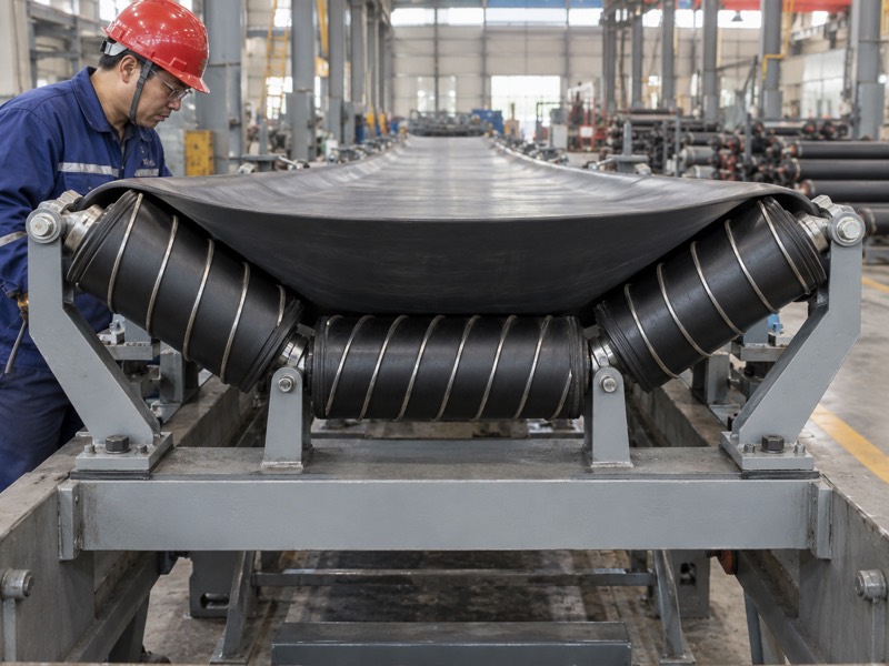
What must you identify before selection?
Identify how your proposed assembly creates correction. Some designs pivot a support frame when belt movement changes contact. Others use a specific roller profile within their own arrangement. If you compare only individual rollers, you may miss what makes either system work.
- Obtain a drawing of the complete tracking mechanism.
- Identify moving parts, sensing contact and mechanical stops.
- Confirm carrying or return duty and belt travel direction.
Then separate component requirements from your desired operating result. A supplier can propose a defined assembly against supplied duty. Stable travel also depends on conditions throughout your conveyor, so document those conditions before purchase.
Which question clarifies the proposal?
| Proposal detail | Question | Required evidence |
|---|---|---|
| Roller profile | How does contact influence travel? | Assembly explanation |
| Pivoting frame | What causes and limits movement? | Mechanism drawing |
| Intended duty | Where can the unit operate? | Application requirements |
Key Takeaway: Compare complete mechanisms. Ask each supplier to explain corrective movement and limits against your actual conveyor duty.
2. What should you check before blaming a tracking roller?
Check where drift starts, whether loading changes it and whether it repeats with belt position. Your conveyor belt tracking rollers may react to faults that begin elsewhere. If your observations identify an upstream cause, repair that cause before adding correction hardware.

How can drift patterns guide inspection?
Use the pattern to choose your next check. Drift under load can point toward off-center feeding or unequal support. A repeated disturbance once per circuit can suggest belt or splice condition. Local drift may relate to one support frame or seized roller.
- Compare empty running with normal loaded conditions.
- Mark where drift begins and where it becomes visible.
- Record any repeat tied to splice passage or a belt mark.
After site-approved lockout/tagout, check geometry and roller rotation. If deposits change contact, remove their cause as well as accumulated material. Keep photos and measurements so you can compare behavior after each repair.
Which pattern deserves which check?
| Pattern | Candidate cause | Check after isolation |
|---|---|---|
| Drifts during loading | Off-center feed | Chute and support |
| Repeats with belt position | Splice or belt damage | Identified belt area |
| Starts near one frame | Skew or seized support | Frame and bearings |
Key Takeaway: Write a short fault record before ordering a trainer. Use it to justify what new hardware should correct.
3. Why does ordinary support alignment still matter?
Ordinary support sets the belt’s approach to a tracking device. Your conveyor belt tracking rollers need consistent upstream and downstream geometry. If nearby frames are skewed, the device may face persistent forces beyond its intended corrective duty.

Which references should maintenance use?
Set a common datum before moving frames. A bent adjacent bracket can give a misleading local reference. Check carrying roller frames and relevant return support against your approved conveyor layout. Then document each adjustment.
- Check mounting security and frame condition before measurement.
- Confirm support geometry across a useful inspection span.
- Inspect roller rotation and deposits after isolation.
Trough shape also affects contact. If supports differ in height or angle, belt loading can become uneven. Use your equipment drawing rather than correcting visible drift through arbitrary skewing.
What should alignment records include?
| Item | Why it affects tracking | Record |
|---|---|---|
| Frame axis | Sets local approach | Datum-based measurement |
| Support height | Changes belt contact | Installed elevation |
| Trough geometry | Distributes support | Approved arrangement |
Key Takeaway: Restore ordinary support before testing corrective hardware. Keep datum and adjustment records with your maintenance work order.
4. How does a pivoting assembly guide the belt?
A pivoting assembly changes support orientation through its designed response to belt contact or sensing movement. Your conveyor belt tracking rollers need free movement and suitable geometry for that response. If a pivot sticks, a sound roller cannot perform the intended correction.
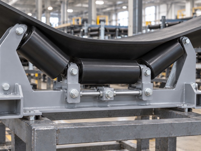
What can block a working mechanism?
Inspect the movement path while equipment is isolated. Dust, corrosion or damaged parts can restrict pivot travel. Poor mounting can also create interference with guards or nearby structure. Check freedom of movement through your approved inspection method.
- Identify pivot, bearings, links and mechanical stops.
- Check clearance through permitted movement.
- Record wear, looseness or binding before adjustment.
Don’t remove stops or alter link lengths without design approval. Those features can limit response and protect surrounding equipment. If their purpose remains unclear, request an assembly drawing before making changes.
Which fault affects which behavior?
| Fault | Likely consequence | Repair check |
|---|---|---|
| Bound pivot | Corrective movement restricted | Free approved travel |
| Worn linkage | Delayed or unstable response | Interface condition |
| Structural interference | Movement stops unexpectedly | Clearance envelope |
Key Takeaway: Check pivot function alongside roller rotation. Approve repairs against the complete mechanism and its specified travel limits.
5. What can a tapered profile contribute to tracking?
A tapered profile can change contact geometry within an assembly designed for that purpose. Your conveyor belt tracking rollers need application-specific confirmation of profile, mounting and belt interaction. A taper used in a package-handling curve performs another job.
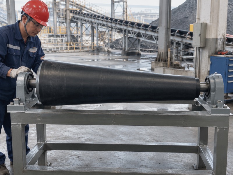
Why should you avoid universal taper claims?
Ask where and how the belt contacts your profile. A conical appearance does not prove automatic centering. Corrective behavior depends on belt contact, support geometry and assembly movement. If a proposal lacks these details, request them before approving its claimed function.
- Identify whether taper belongs to belt support or package conveying.
- Obtain profile dimensions and installation orientation.
- Confirm assembly movement and permitted belt contact.
Curve-conveyor tapers accommodate different travel across package width. That explanation does not establish bulk-belt training behavior. Keep each proposed product tied to its intended duty and complete installation.
Which application requires which review?
| Taper application | Primary relationship | Review document |
|---|---|---|
| Package conveyor curve | Surface speed across turning path | Curve layout |
| Belt-training assembly | Designed contact and response | Complete assembly |
| Replacement component | Existing installation geometry | Controlled drawing |
Key Takeaway: Treat taper as one part of a defined mechanism. Ask for written application suitability rather than a general self-centering claim.
6. How much contact should a tracking unit have?
A tracking unit needs contact defined by its own design and belt requirements. Your conveyor belt tracking rollers have no universal pressure or height setting. If contact seems weak or excessive, compare installed geometry with approved instructions before altering support height.
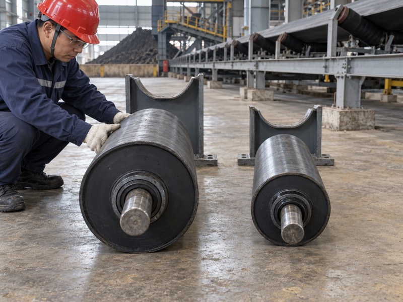
What makes contact effective or harmful?
Check belt engagement before increasing force. Roller elevation, nearby spans and belt tension affect how contact develops. Too little engagement may reduce response. Excessive or uneven loading can create wear, so changes need engineering approval.
- Check elevation against adjacent support and assembly drawings.
- Inspect contact across the intended working face.
- Record belt-edge wear, cover marks or abnormal deflection.
If you use sensing rollers, their edge contact also needs review. Don’t tighten them merely because a belt still drifts. Persistent contact can indicate unresolved loading or alignment rather than insufficient restraint.
What should contact observations show?
| Observation | Question | Next check |
|---|---|---|
| Little engagement | Does geometry match installation? | Elevation and span |
| Uneven contact | Is support or loading unequal? | Frame and belt profile |
| Heavy edge rubbing | Does drift exceed intended response? | Conveyor fault review |
Key Takeaway: Adjust only through approved settings. Record contact conditions before and after changes so their effect remains clear.
7. Can one tracking arrangement handle reverse travel?
Only an arrangement approved for reversing duty should be used in both directions. Your conveyor belt tracking rollers may depend on direction-sensitive geometry or sensing. Reverse travel can change approach conditions and how correction develops.

What should your duty description include?
State direction changes before requesting a quotation. Include normal operating directions and whether loaded travel occurs in each. Nearby loading and discharge conditions may also change with direction. Then ask your supplier to confirm suitable assembly behavior.
- Identify one-way or reversing conveyor duty.
- Provide relevant loading points and support layout.
- Record any approved direction-change procedure.
Don’t infer reversing suitability from a symmetrical-looking roller. Linkages, pivots and sensing positions may have different effects during reverse travel. A friction-based tracking assembly also requires specific application confirmation.
Which reversing detail needs confirmation?
| Duty detail | Possible effect | Supplier confirmation |
|---|---|---|
| Loaded reverse travel | Changes approach conditions | Approved application |
| Direction-sensitive sensing | Changes corrective response | Mechanism suitability |
| Multiple loading points | Changes drift source | Layout review |
Key Takeaway: Put reversing duty in your inquiry. Obtain a clear written response before testing an assembly in another direction.
8. What wear checks should you include in maintenance?
Include roller rotation, surface condition, pivot freedom, mounting security and belt contact evidence. Your conveyor belt tracking rollers operate as assemblies, so inspection must cover their moving interfaces. If you inspect only bearings, another fault may still prevent correction.

How can records improve repair decisions?
Compare wear with where contact occurs. A polished edge guide and a seized support roller tell different stories. Look for repeated damage at specific locations. Then connect those findings with your documented drift pattern and operating conditions.
- Record rough rotation, damaged seals and surface deposits.
- Check pivot wear and permitted movement.
- Photograph belt marks and installed contact height.
Use cleaning and lubrication methods allowed by your assembly instructions. If bearings are sealed without a service provision, added grease may be unsuitable. Keep dust and damaged parts away from a repaired mechanism during refitting.
What does each wear sign suggest?
| Wear sign | Possible issue | Inspection focus |
|---|---|---|
| Rough roller rotation | Bearing or seal fault | Rotating component |
| Pivot looseness | Worn supporting interface | Mechanism geometry |
| Repeated belt-edge marks | Excessive or misplaced contact | Contact and drift |
Key Takeaway: Inspect the whole assembly. Pair component wear with belt observations before choosing repair or replacement.
9. How should you test a selected tracking device?
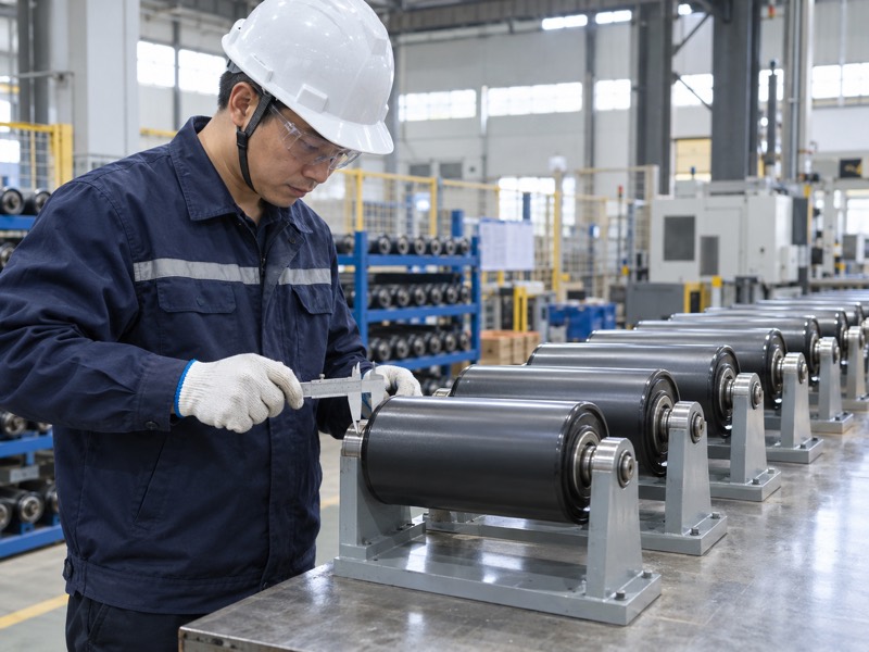
Test it after correcting known faults and confirming installation against approved requirements. Your conveyor belt tracking rollers need a controlled trial under relevant duty. An empty belt that briefly appears centered provides incomplete evidence.
Which trial sequence gives useful evidence?
Keep a baseline before changing settings. Record belt position and operating conditions. Then change one approved setting at a time after isolation. Observe from safe positions and keep guards installed during operation.
- Confirm mounting, contact geometry and movement limits.
- Observe relevant empty and loaded operation.
- Record contact, correction behavior and any recurring drift.
If the belt hunts or contact grows heavy, stop adjustment and review causes. Multiple simultaneous changes can obscure the fault. Use your supplier’s instructions and site commissioning procedure for any further trial.
What should acceptance compare?
| Trial area | Baseline | Acceptance reference |
|---|---|---|
| Belt path | Position before repair | Approved operating envelope |
| Assembly movement | Initial contact and travel | Mechanism limits |
| Wear evidence | Existing belt marks | No unacceptable contact |
Key Takeaway: Agree observable acceptance conditions before testing. Retain baseline and final results so you can judge actual change.
10. What belongs in your tracking-roller purchase package?
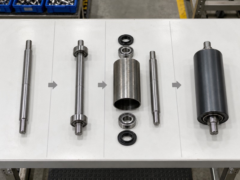
Your package needs belt details, drift records, layout, assembly drawings and acceptance requirements. Your conveyor belt tracking rollers should be selected against defined duty. If uncertainty remains about root cause or mounting, resolve it before treating a quotation as ready for ordering.
How should you close technical gaps?
Ask suppliers to state fit and limits in writing. Define whether scope includes rollers, frame, sensing components and mounting hardware. Request any deviations against your drawing. Then agree which inspections and trials will support acceptance.
- Provide belt width, construction, speed and operating directions.
- Include loading conditions and environmental exposure.
- Define mounting interfaces and required inspection records.
Procurement and maintenance should review the same configuration. If your installed layout changes later, update its record before reordering. This keeps replacement decisions tied to actual equipment rather than an old product name.
Which requirement prevents which mismatch?
| Requirement | Mismatch prevented | Approval record |
|---|---|---|
| Complete assembly scope | Missing mechanism parts | Supply list |
| Duty and layout | Unsuitable application | Technical confirmation |
| Inspection and trial plan | Undefined acceptance | Agreed criteria |
Key Takeaway: Purchase a defined assembly for a defined duty. Close drawing and acceptance gaps before placing your order.
FAQ
Q1: Can a tracking roller correct every drifting belt? No. Loading, alignment, belt condition and support faults also need repair.
Q2: What’s the best place for a trainer? Use the approved layout. Contact, approach geometry and duty determine suitable positions.
Q3: Can I raise a trainer to improve contact? Only within approved instructions. Changed height also changes belt loading and nearby geometry.
Q4: How do I choose taper versus pivoting support? Compare complete mechanisms against your duty. Neither appearance alone nor a product label proves suitability.
Q5: Can I use one design in both directions? Only with confirmed reversing suitability. Include both directions in your technical inquiry.
Send your belt details, drift record and assembly drawing when you contact us about tracking-roller selection.