
tapered conveyor rollers have working diameters that vary along their length, allowing different surface speeds across a curved conveying path. If your replacement fits its brackets but cartons skew through a turn, geometry may still be wrong. Check taper, curve layout and load support together before approving interchangeability.
1. What do tapered conveyor rollers mean in your application?
In a roller conveyor, tapered conveyor rollers usually support loads moving through a curve. Other conveyor assemblies may use tapered elements for different guiding functions. You must identify application and assembly geometry before interpreting a product description.
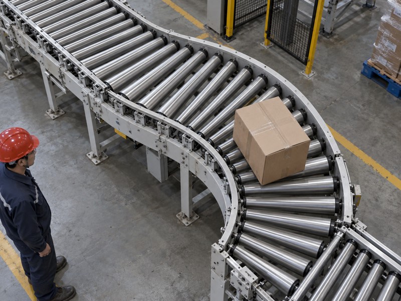
Which product are you actually replacing?
Name the assembly before measuring its component. A tapered roller bearing belongs inside a bearing arrangement and does not provide a conveyor’s exposed load-supporting surface. A belt-training assembly also requires its own mechanism and mounting details. Similar names do not establish interchangeable functions.
- State whether loads rest directly on roller surfaces.
- Identify curved roller conveying or a belt-support arrangement.
- Include photographs showing complete installation and operating direction.
If your conveyor uses a different taper function, ask for a matching application review. Do not transfer curve-conveyor assumptions into a bulk-belt drawing. Suppliers need enough context to identify which geometry they should quote.
How do similar terms differ?
| Product term | Typical role | Drawing to provide |
|---|---|---|
| Curve conveyor roller | Supports turning loads | Conveyor layout |
| Tapered roller bearing | Supports rotating machine parts | Bearing arrangement |
| Tapered belt-support element | Works within a specific assembly | Complete support assembly |
Key Takeaway: Identify component duty before requesting a taper. Include its surrounding assembly so a quotation addresses your actual installation.
2. Why does a curve require different surface speeds?
A load’s outside edge travels farther than its inside edge while moving around a curve. Your tapered conveyor rollers provide different local surface speeds along their working face. Correct geometry helps accommodate that difference while limiting unwanted slip or load rotation.
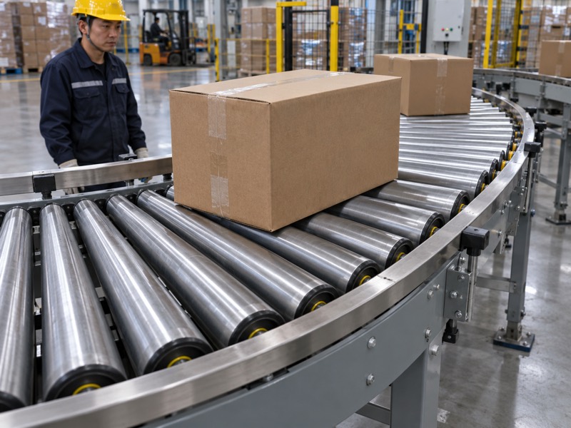
What creates the speed difference?
Compare travel distance across your load. Points farther from a curve’s center follow longer arcs. On a rotating roller, a larger working radius provides higher local surface speed at a given rotational speed. Your taper should relate these conditions through its intended curve geometry.
- Identify inner and outer conveying radii.
- Confirm which end has the larger working diameter.
- Review load width and intended path through the curve.
Real conveying still depends on contact, friction and load condition. Geometry alone cannot guarantee every package follows an ideal path. Soft bottoms, contamination and incorrect drive arrangements can change motion despite a correctly manufactured taper.
What does each geometric feature control?
| Feature | Mechanical relationship | Buyer check |
|---|---|---|
| Inner curve radius | Shorter travel path | Layout dimensions |
| Outer curve radius | Longer travel path | Load envelope |
| Diameter variation | Local surface-speed variation | Approved taper profile |
Key Takeaway: Relate taper to your actual curve layout. Ask engineering to confirm geometry rather than copying end diameters from an unrelated conveyor.
3. Which way should the larger roller end face?
For a conventional radial curve arrangement, the larger end faces its outside arc. Your tapered conveyor rollers still need installation confirmation against an approved drawing. Different mechanisms or transfer geometries may require their own arrangement.
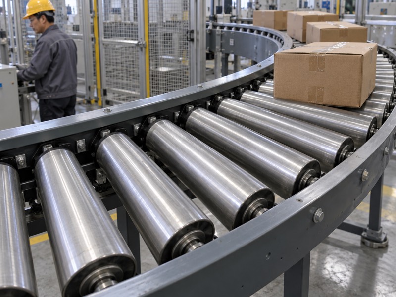
What happens when orientation changes?
Check large-end position before reviewing wear. Reversed tapers create a surface-speed distribution inconsistent with normal curve travel. Loads may scuff, skew or press against side guidance. Incorrect mounting can also change shaft position even if diameter orientation appears right.
- Mark inside and outside locations on installation drawings.
- Identify conveyor direction and any reversing duty.
- Confirm shaft ends match their corresponding frame interfaces.
Your crew should not infer orientation from packaging labels alone. Keep an installation reference with spare inventory. After fitting, inspect clearances and rotation before controlled load trials.
Which installation detail prevents confusion?
| Detail | Potential error | Confirmation |
|---|---|---|
| Large-end location | Reversed taper | Outside-arc drawing |
| Shaft-end geometry | Incorrect frame interface | Installation section |
| Operating direction | Unsuitable drive arrangement | Machine duty record |
Key Takeaway: Verify orientation and shaft interfaces together. Require drawings that remain understandable when a spare reaches maintenance during a shutdown.
4. How do curve radius and roller length interact?
Curve radius and working length define where each part of a taper contacts moving loads. Your tapered conveyor rollers must fit that relationship as well as available frame width. A correct overall length does not prove your working face matches intended travel geometry.
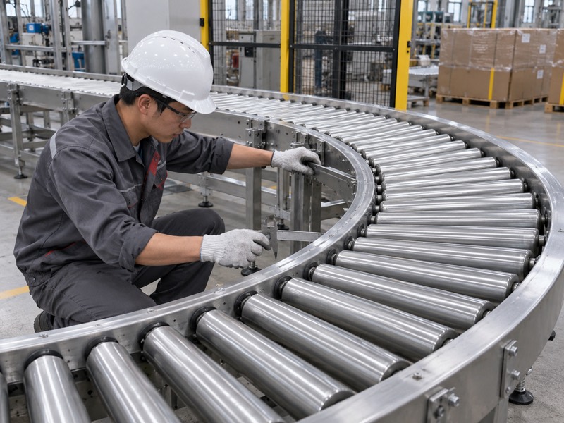
Which length should your drawing identify?
Distinguish working face from total assembly length. Shaft projections, bearings and mounting features may extend beyond load contact. Specify each dimension against a clear datum. Include transition points where taper or surface construction changes.
- Record working-face length and mounting length separately.
- Show inner and outer frame locations relative to curve center.
- Define any straight section, sleeve or shoulder on your roller.
Load positioning also affects which part of a taper carries weight. Narrow products may contact only part of its working face. Review expected product positions rather than assuming each carton stays centered throughout a turn.
What belongs in a geometry package?
| Dimension | Purpose | Common omission |
|---|---|---|
| Working-face length | Defines load contact | Confused with shaft length |
| Overall mounting length | Defines installation fit | Unclear end datum |
| Inner and outer radii | Defines curve relationship | Missing center reference |
Key Takeaway: Specify curve layout and working-face dimensions together. Resolve unclear length references before comparing supplier drawings.
5. Which diameters and taper profile should you measure?
Measure small-end diameter, large-end diameter and profile at defined axial positions. Your tapered conveyor rollers need a documented working shape rather than a general taper label. Existing wear can distort measurements from a used component.
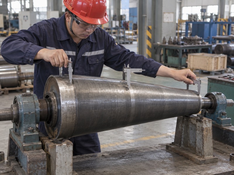
How do you avoid copying wear into a new part?
Use an approved drawing whenever one exists. If only a used sample remains, identify wear and damaged areas before measuring. Check multiple locations and document which values represent nominal geometry. Don’t let one flattened surface become a replacement specification.
- Measure end diameters away from damaged contact patches.
- Record measurement positions along the working face.
- Separate surface wear from intended steps or sleeves.
A taper may use formed tube, sleeves or another approved construction. Confirm how its surface geometry is maintained under intended loads. Ask suppliers to disclose construction differences that affect contact, stiffness or replacement fit.
Which measurement answers which question?
| Measurement | Question | Follow-up |
|---|---|---|
| Small-end diameter | What fits the inner contact? | Compare nominal drawing |
| Large-end diameter | What supports outer travel? | Check wear condition |
| Intermediate profile | How does diameter vary? | Agree measurement positions |
Key Takeaway: Quote nominal taper geometry from a controlled reference. Use worn samples as evidence requiring interpretation rather than automatic dimensional masters.
6. How should shaft and bearing arrangements be specified?
You should specify shaft type, end features, mounting interfaces and bearing arrangement separately from roller profile. Your tapered conveyor rollers can have different rotating and stationary components. Those differences affect installation, support and maintenance even when external dimensions look similar.
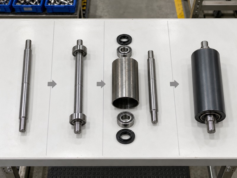
What can make a replacement incompatible?
Inspect the interfaces hidden at each end. End flats, slots, threads or fixing methods can determine retention. Bearing locations determine how loads reach supporting frames. A replacement with altered shaft or bearing geometry may fit loosely or require unapproved frame changes.
- Define shaft diameter and end-feature dimensions.
- Identify stationary or rotating shaft arrangement.
- Record bearing positions and permitted maintenance provisions.
Review supplier technical capability through drawings and inspection evidence relevant to your part. Ask who supplies spacers, retainers and mounting hardware. These items belong in a complete installation package when their absence changes fit.
What should interface approval include?
| Interface | What to confirm | Acceptance evidence |
|---|---|---|
| Shaft ends | Retention and mounting fit | Dimensioned detail |
| Bearing arrangement | Supported loading and rotation | Approved assembly |
| Associated hardware | Complete installation | Defined supply scope |
Key Takeaway: Approve shaft and bearing interfaces explicitly. A matching taper profile cannot compensate for incompatible installation details.
7. How do product bottoms and roller spacing affect support?
Product bottoms and spacing determine how loads bridge gaps while moving through a curve. Your tapered conveyor rollers must support the intended product range. Outside-arc gaps can differ from gaps near the inside frame.
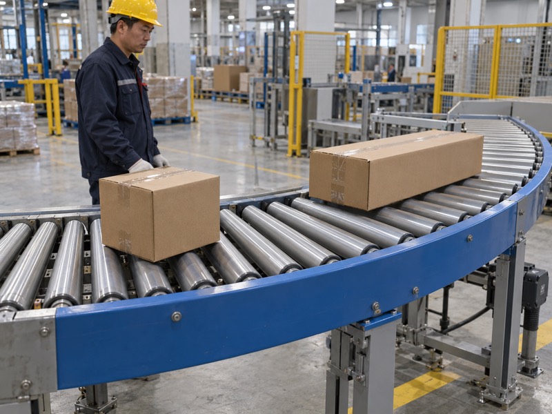
Which products challenge your arrangement?
Check the smallest usable contact footprint. Short cartons, flexible packaging or irregular bases may lose stable support between rollers. A nominal package length can differ from its actual flat contacting area. Test representative products in their expected orientation.
- Document minimum and maximum product contact footprints.
- Include load mass and any uneven weight distribution.
- Review support during entry, curve travel and exit.
Support requirements come from conveyor design and product behavior. Don’t apply an unsupported universal roller-count rule. Confirm acceptance through layout review and controlled handling tests using loads approved for your equipment.
Which product detail changes support?
| Product feature | Support concern | Review action |
|---|---|---|
| Short contact footprint | Bridges fewer gaps | Check curve spacing |
| Flexible bottom | Sags between rollers | Trial representative load |
| Uneven weight | Concentrates contact | Review loading positions |
Key Takeaway: Specify the full product range, including bottom geometry. Evaluate support through the curve rather than only on a straight approach.
8. Which drive details must remain compatible?
Drive grooves, sprockets, belts and transmission locations must match your conveyor’s approved arrangement. Your tapered conveyor rollers used in powered curves need more than correct external taper. Gravity applications require different checks because available motion depends on slope and resistance.
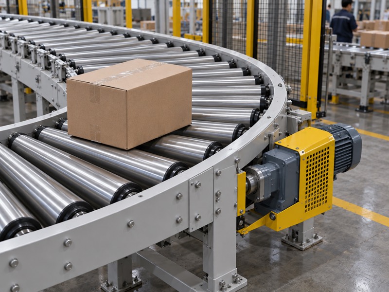
What should you verify on powered equipment?
Match transmission interfaces before comparing roller prices. Drive position and geometry affect how motion reaches each roller. A proposed change may alter clearance or belt alignment. Obtain machine-builder approval when replacement details depart from your existing design.
- Identify drive method and interface dimensions.
- Record transmission position relative to mounting datums.
- Confirm guarding and service access after installation.
For gravity curves, review slope, bearing resistance and product behavior together. A taper does not create continuous propulsion on a level path. Controlled trials should confirm acceptable movement and stopping arrangements for your actual loads.
How do powered and gravity duties differ?
| Duty | Motion source | Required review |
|---|---|---|
| Powered curve | Defined transmission | Drive-interface fit |
| Gravity curve | Available gravitational component | Slope and rolling resistance |
| Controlled accumulation | Specific conveyor system | Load and control integration |
Key Takeaway: State how rollers receive motion. Get explicit approval for any replacement that changes transmission geometry or operating behavior.
9. What environment and wear conditions affect selection?
Moisture, abrasive deposits and cleaning conditions can affect surfaces, bearings and mounting hardware. Your tapered conveyor rollers need material and sealing proposals matched with that exposure. General labels such as heavy duty do not define a measurable requirement.

Which exposure details should you record?
Describe where contamination reaches the roller. Water from cleaning differs from occasional ambient moisture. Fine dust near end seals creates another duty. Include actual cleaning methods and chemicals when requesting a suitable construction.
- Record moisture, dust and abrasive-material exposure.
- State cleaning method and any chemical contact.
- Identify surface marking or corrosion observed on removed parts.
Inspection frequency depends on operating conditions and site maintenance procedures. Watch changing rotation, surface deposits and looseness. Record findings before wear removes evidence needed for your next replacement decision. Follow site-approved lockout/tagout before physical checks.
What exposure calls for clarification?
| Exposure | Concern | Supplier question |
|---|---|---|
| Washdown or chemical cleaning | Material and seal compatibility | Approved cleaning limits |
| Abrasive deposits | Surface and bearing contamination | Protection proposal |
| Damp storage | Corrosion before installation | Packaging and storage method |
Key Takeaway: Provide actual exposure conditions instead of a broad duty label. Request documented material and maintenance recommendations.
10. How do you approve a tapered roller replacement?
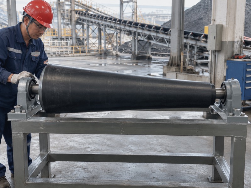
You approve it through drawing agreement, dimensional inspection and a controlled conveyor trial. Your tapered conveyor rollers need confirmation of geometry, interfaces and product handling. Acceptance should identify what you will inspect before shipment and what operations will verify after installation.
Which records should follow your order?
Define acceptance while the quotation remains reviewable. Ask suppliers to identify drawing revisions and any proposed deviations. Include measurement methods for dimensions or runout where required. Prepare a technical inquiry with layout and operating records.
- Agree drawing, supply scope and inspection evidence.
- Verify dimensions and rotation upon receipt.
- Trial representative products within approved procedures.
Keep results linked with part identity and installed location. Later maintenance can then distinguish component variation from conveyor adjustment. A clear acceptance record also helps procurement compare future proposals against the same requirements.
What supports an approval decision?
| Stage | Evidence | Decision |
|---|---|---|
| Quotation | Controlled drawing and deviations | Approve proposed fit |
| Receipt | Inspection against agreed methods | Release for installation |
| Commissioning | Representative product handling | Accept specified duty |
Key Takeaway: Approve a defined component and application together. Preserve drawings and trial records for future replacement orders.
FAQ
Q1: Can I replace a taper with a straight roller? Only with engineering approval. A straight surface changes speed distribution across a curved path.
Q2: How do I identify the outside end? Use your curve drawing. Conventional radial layouts place a larger working diameter toward the outside arc.
Q3: Can I order from end diameters alone? No. Working length, shaft interfaces, curve layout and drive details also affect fit.
Q4: What’s the best sample for measurement? An unworn controlled reference helps. Document damage and uncertainty when only a used roller remains.
Q5: Do tapered rollers automatically track belts? No universal behavior applies. Belt training depends on complete assembly geometry and operating conditions.
Send your curve layout and existing roller drawing when you contact us about a replacement geometry review.