
Choose impact idlers or an impact bed by reviewing material arrival, belt stability, sealing and service access together. Idlers provide rolling support at stations; a bed provides sliding support across its designed contact area. Each needs a duty assessment. If your loading zone leaks or suffers repeated damage, identify the cause before selecting a different support system.
1. How do impact idlers and impact beds support a belt?
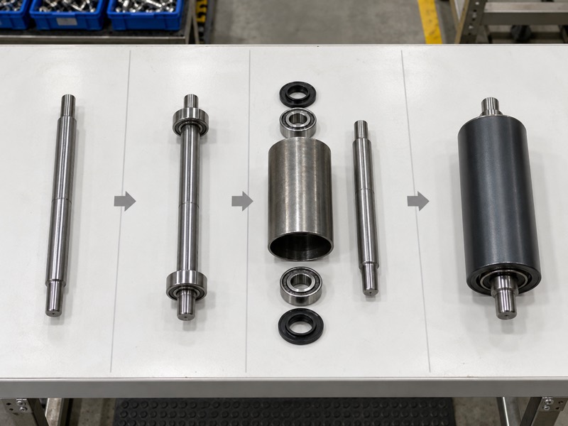
Your impact idlers support a belt through rotating rubber-ring rollers, while an impact bed uses fixed support surfaces beneath it. Both transfer load into a supporting frame. Their contact patterns differ, so their effects on belt movement and resistance differ too. Review the complete arrangement rather than comparing only visible rubber or advertised impact descriptions.
Which contact difference should you understand?
Separate rolling contact from sliding contact. A freely turning idler rolls under the belt. A bed’s working surface contacts a belt that slides across it. Because construction varies, ask for contact material, geometry and duty limits for each candidate rather than treating every impact bed as identical.
- Identify roller or fixed-surface contact geometry.
- Confirm load paths through shafts, bars and frames.
- Record belt shape and required support region.
Why compare complete systems?
Frame fit, belt clearance and maintenance access affect either choice. A support surface that suits impact may still be unsuitable if its arrangement changes belt elevation or conflicts with existing skirts.
| System | Main contact | Review focus |
|---|---|---|
| Impact idlers | Rotating resilient rollers | Station coverage and assembly duty |
| Impact bed | Fixed sliding surfaces | Contact material and belt stability |
| Either system | Frame-supported load path | Fit and transfer compatibility |
Key Takeaway: Compare contact mechanism and complete support geometry before evaluating impact capacity claims.
2. Which system better supports skirt sealing?
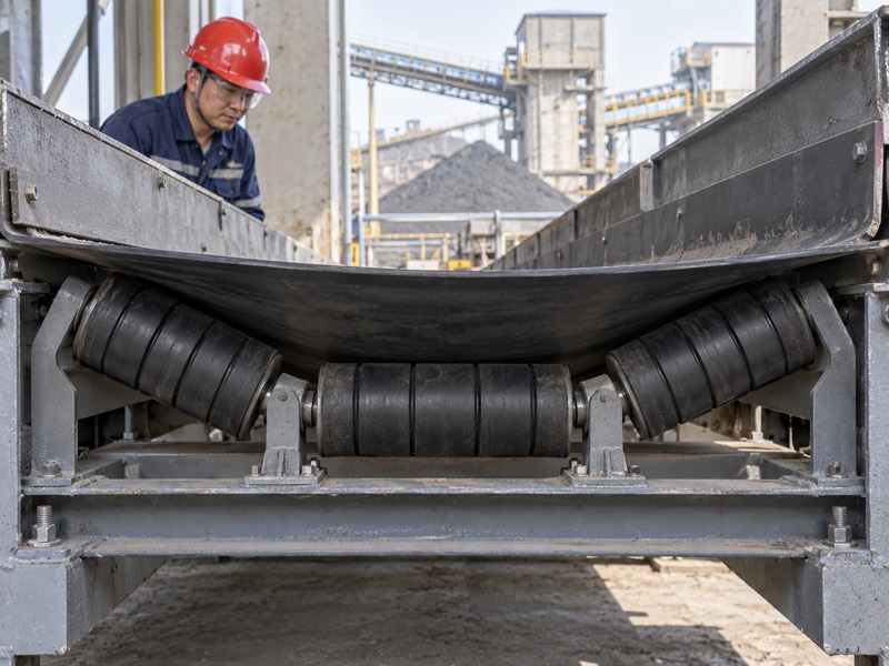
The better sealing support depends on whether impact idlers or a bed provide adequate belt stability beneath your skirts. Roller stations leave spans between contacts; a bed can provide more continuous support within its designed area. However, sealing also depends on skirt arrangement and material loading. A bed alone doesn’t establish a correct seal or eliminate leakage.
What should you check at a leaking loading zone?
Locate where belt movement affects skirt contact. Record whether leakage occurs between supports, near a transfer edge or along a damaged seal. Then review support elevation and approved skirt settings. Tightening skirts to compensate for unstable support can add unwanted contact and wear without addressing the original condition.
- Mark leakage locations and belt movement.
- Check support coverage beneath the skirt region.
- Inspect skirt material and approved adjustment.
How do you establish the required support area?
Use your loading-zone layout and safe observations. If the sealing region extends beyond impact support, review its full length with your designer. Adjacent support may need consideration even when the main impact component remains unchanged.
| Leakage evidence | Support question | Additional check |
|---|---|---|
| Between stations | Is belt movement excessive? | Support arrangement |
| At seal damage | Is contact surface sound? | Skirt condition |
| Outside supported area | Is coverage sufficient? | Loading-zone layout |
Key Takeaway: Compare sealing-zone stability and skirt condition together before choosing a bed as a leakage remedy.
3. How should material arrival influence your choice?
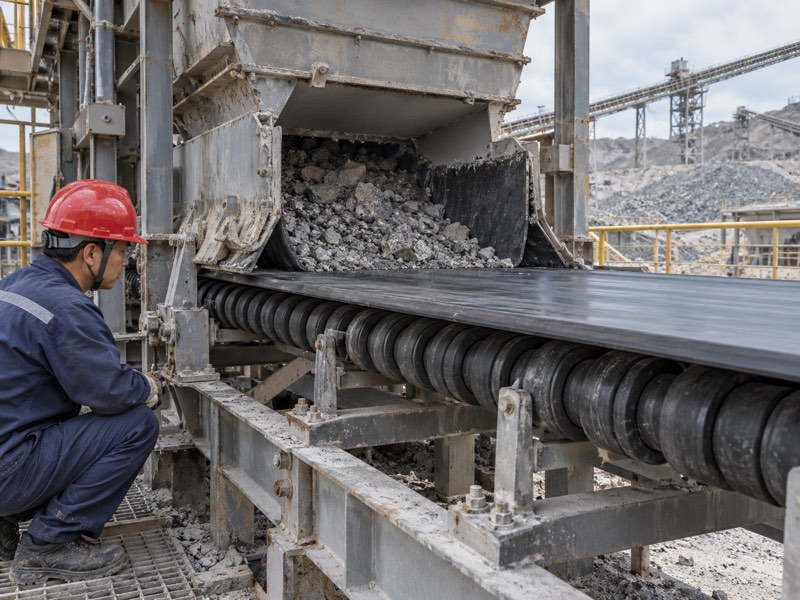
Material arrival should influence impact idlers or bed selection through lump characteristics, incoming motion and landing position. Concentrated heavy lumps and a broad fines stream create different support demands. Drop height alone cannot define either system’s suitability. Provide your transfer designer with material and geometry inputs, then compare constructions against an approved duty.

Which transfer conditions should you document?
Show where force reaches the support. Map the expected landing region against rollers or bed bars. If the flow changes after chute wear or adjustment, include that change in your assessment. A component substitution may still face the same poorly aligned material stream unless transfer geometry receives attention.
- Describe material mass, size and shape.
- Show arrival direction and receiving belt motion.
- Mark normal and irregular landing regions.
What can a supplier assess from those inputs?
Ask for a construction proposal with stated assumptions and limits. Then check whether its rating applies to the whole support system or an individual part. Keep uncertain input values visible until your responsible engineer resolves them.
| Transfer input | Design purpose | Comparison question |
|---|---|---|
| Lump characteristics | Concentrated demand | Which construction suits duty? |
| Arrival motion | Force and belt interaction | What assumptions apply? |
| Landing region | Required support coverage | Is impact beneath support? |
Key Takeaway: Compare both systems against the same verified transfer duty and landing region.
4. How do resilient components differ between systems?
Resilient components in impact idlers and beds differ by construction, contact geometry and how load passes into their frames. Rubber rings form a roller’s working surface. Bed designs may combine a sliding contact layer with resilient supporting material. Those arrangements need their own specifications; visual thickness or softness cannot establish suitable impact response or service life.
What should you ask about resilient materials?
Request properties relevant to your application. Heat, chemicals and abrasive material can affect both rubber and sliding surfaces. If a bed uses several material layers, ask how its offered construction is assembled and inspected. Ring and bar retention also matter because loose working components can change belt support.
- Identify contact and resilient materials separately.
- Describe thermal, chemical and abrasion exposure.
- Confirm retention and replacement requirements.
How can you avoid a misleading material comparison?
Compare complete constructions under the same duty, rather than comparing rubber thickness alone. A stated performance result needs its test conditions and applicability reviewed before you use it as selection evidence.
| Component | Useful question | Evidence |
|---|---|---|
| Roller rings | What material and geometry apply? | Ring specification |
| Bed contact layer | What sliding conditions apply? | Bar construction |
| Support material | How does load reach the frame? | System design details |
Key Takeaway: Compare documented component constructions and duty limits, rather than judging impact response from appearance.
5. How should either system fit your belt path?
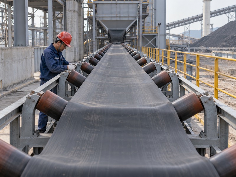
Both impact idlers and beds should fit your approved trough shape, elevation and neighboring belt supports. Abrupt geometry changes can disturb contact or introduce unfavorable belt conditions. If a support replacement changes height, check skirts and nearby components again. Your conveyor designer should approve the complete loading-zone arrangement before installation.
Which interfaces should your layout show?
Follow your belt through each loading zone. Mark where support begins and ends, including its transition to carrying idlers. Check belt manufacturer requirements where relevant. A support product drawing alone won’t describe every adjacent frame or contact change on your conveyor.
- Record trough geometry and support elevation.
- Include first and last support contact positions.
- Show neighboring carrying stations and skirts.
What should a retrofit drawing establish?
It should show mounting interfaces and the resulting belt path. If dimensions differ from current equipment, list those changes explicitly. Then approval can address their effects rather than relying on an assumed drop-in fit.
| Layout item | Possible change | Review |
|---|---|---|
| Support height | Belt elevation | Adjacent component clearance |
| Trough geometry | Belt contact shape | Belt compatibility |
| Support boundary | Contact transition | Complete loading-zone layout |
Key Takeaway: Approve how either system joins the existing belt path, including elevation, troughing and support boundaries.
6. What resistance changes should you consider?
Consider operating resistance when comparing impact idlers with beds because rotating and sliding contact behave differently. A freely rotating roller and a fixed contact bar impose different conditions on your belt. Contamination, contact pressure and material choice also affect resistance. Ask your conveyor engineer to assess drive and belt implications rather than assuming either system has a fixed universal energy advantage.
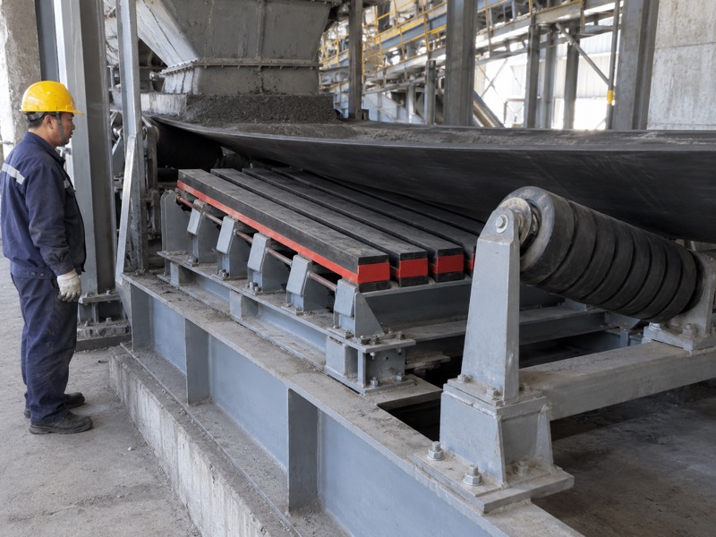
What information helps assess sliding contact?
Use the proposed contact conditions. State belt speed, material, contact area and expected loading. If a supplier offers friction data, request its measurement conditions. Then your engineer can judge how that information relates to the actual bed construction, wear state and operating exposure.
- Provide belt speed and working contact details.
- Describe contamination and expected contact pressure.
- Request applicable friction and operating limits.
Why do roller faults belong in this comparison?
A stopped roller creates sliding contact too, so maintenance condition affects idler operation. Use realistic service assumptions for both candidates. A comparison of a new bed with failed rollers doesn’t establish a general ranking.
| Condition | Resistance concern | Required assessment |
|---|---|---|
| Free rolling idler | Bearing and rolling resistance | Complete assembly duty |
| Fixed bed surface | Sliding contact | Material and contact conditions |
| Seized roller | Belt sliding over shell | Fault correction |
Key Takeaway: Review drive and belt implications using actual contact conditions and realistic maintenance assumptions.
7. How does maintenance access affect the decision?
Maintenance access affects impact idlers or bed selection because crews need safe ways to inspect, clean and replace their working components. Constrained transfer structures can make either system difficult to service. Retractable features may help only within their approved method. They don’t remove the need to control hazardous energy and retained material before work.
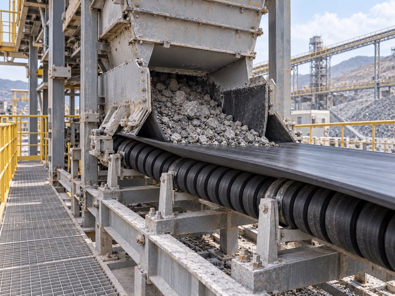
Which service tasks should you compare?
Check the actual removal route. Follow site-approved lockout and tagout procedures before close checks or replacement. Then review clearance, lifting needs and belt support during work. Ask for instructions covering the specific offered construction, rather than assuming a slide-out feature can be used during production.
- Compare access to rings, bars and fasteners.
- Confirm withdrawal space and handling method.
- Review isolation and belt-support requirements.
How should you compare maintenance effort?
List tasks and required access, without assigning unsupported savings. Include effects on nearby return-side supports where falling material creates buildup. A complete cleanup plan may matter as much as a convenient component feature.
| Task | Idler consideration | Bed consideration |
|---|---|---|
| Inspection | Rotation, rings and ends | Bars, surface wear and retention |
| Cleaning | Shell and end deposits | Bar gaps and frame deposits |
| Replacement | Roller handling | Bar or assembly handling |
Key Takeaway: Choose a system your crew can service safely through a documented access and handling method.
8. Can an impact bed replace idlers without frame changes?
An impact bed may require frame changes when replacing impact idlers because its mounts, envelope and load path can differ. A nominal belt width doesn’t establish retrofit fit. Check crossmembers, fasteners, skirts and guards in the proposed arrangement. If structural changes are needed, your responsible engineer should approve them before purchasing or installation.
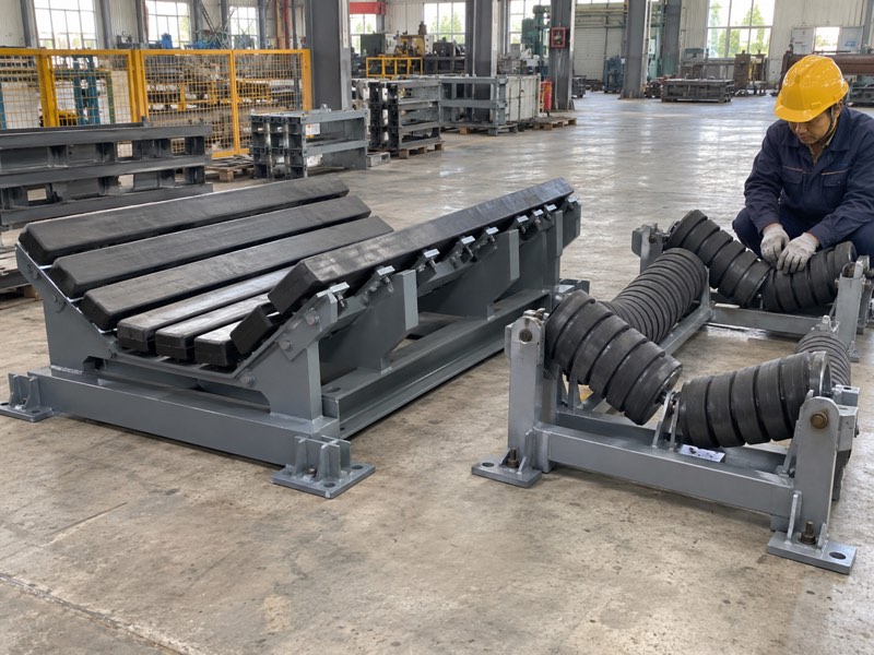
What should a retrofit survey include?
Measure the receiving structure before assuming fit. Record sound mounting points and any distortion from previous service. If a bed changes load introduction, ask for structural assessment. Damaged frames also need repair independent of which support system you select; new components don’t restore cracked or bent steelwork.
- Measure frame span, mounts and available envelope.
- Inspect structural damage and fastener condition.
- Record required changes to guards or skirts.
How should supplier drawings handle deviations?
List each changed interface and proposed adaptation. Then compare it with your site drawing and approved work scope. Keep any welding or drilling requirements within the reviewed structural modification process.
| Retrofit item | Possible difference | Approval basis |
|---|---|---|
| Mounts | New fixing locations | Structural drawing |
| Envelope | Changed service clearance | Installation layout |
| Load path | Different frame reactions | Engineering assessment |
Key Takeaway: Treat a bed retrofit as a documented installation change until drawings establish compatibility and required structural work.
9. What should you inspect after selecting either system?
After selecting impact idlers or a bed, inspect drawing conformity, working surfaces, retention and installed belt support before release. Each system needs construction-specific checks. Roller rotation matters for idlers, while bar condition and fixing matter for beds. Agree on acceptance methods before manufacture, then verify installation through your site’s approved process.
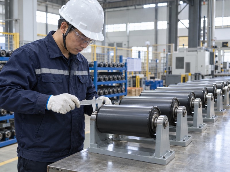
Which checks belong before operation?
Confirm the arrangement you approved is installed. Verify elevation, contact geometry and complete fastenings. Restore guards and remove tools before following restart procedures. If your selection aimed to reduce belt movement or leakage, define safe observations that can confirm whether its intended condition changed.
- Check fit, contact surfaces and restraints.
- Confirm support boundaries and skirt clearances.
- Record safe restart observations against original symptoms.
What should a controlled evaluation measure?
Use your approved acceptance plan and comparable operating conditions. Document remaining issues without attributing every result to the new support. Feed, moisture and belt condition may have changed during the same period.
| Check | Idler focus | Bed focus |
|---|---|---|
| Working surface | Rings and rotation | Sliding layer and bar wear |
| Retention | Shaft seating | Bar and frame fixing |
| Operation | Support and contact | Stability and contact |
Key Takeaway: Verify both construction-specific fit and the operating symptom that prompted your selection.
10. How should you decide between impact idlers and beds?
Decide between impact idlers and beds after reviewing duty, sealing support, resistance, retrofit work and maintenance access together. Either proposal should state assumptions and limits. If one cannot confirm belt or structural compatibility, resolve that gap before approval. Your comparison then has a defined technical basis alongside commercial terms.
What should your quotation request contain?
Give both proposals the same operating basis. Attach transfer geometry, belt details and site interface dimensions. Include the specific problem you want addressed, with its recorded evidence. Then request proposed construction and any required installation changes so you can assess the complete job.
- Supply transfer and material conditions.
- Provide mounting, belt and service-access details.
- State inspection and operating verification requirements.
How can approval support repeat orders?
Keep accepted drawings, materials and application conditions together. Later replacement orders can then refer to the approved system rather than a generic impact support name. Any substitution should receive the same compatibility review.
| Decision area | Required confirmation | Approval record |
|---|---|---|
| Duty | Transfer and belt suitability | Application conditions |
| Retrofit | Fit and structural changes | Accepted layout |
| Service | Safe maintenance and acceptance | Work and inspection plan |
Key Takeaway: Approve the complete loading-zone arrangement, including installation changes and safe service requirements. For an impact-idler quotation, contact us with your transfer layout, belt details and frame measurements. Request a construction proposal that identifies fit requirements and the conditions behind its recommendation.
FAQ
Q1: Can an impact bed guarantee no skirt leakage? No. Belt stability, skirt condition and transfer geometry all need review.
Q2: Are impact idlers always easier to maintain? No. Access, handling and the offered construction determine your service tasks.
Q3: Can I compare support systems by rubber thickness? No. Compare complete materials, geometry, duty assumptions and load paths.
Q4: How do I know whether a bed fits my frame? Use a retrofit drawing covering mounts, structural reactions, clearances and required modifications.
Q5: What’s the best starting point for selection? Document material arrival and the loading-zone problem, then review both proposals against those conditions.