
Choose and inspect guide rollers by checking their mating surfaces, mounting fit, runout and intended load direction. A roller that fits its shaft can still bind against a rail or damage a contacting belt edge. Define what it guides before comparing parts. Then use approved drawings and service requirements to judge the complete arrangement rather than its outside diameter alone.
1. What should guide rollers guide in your equipment?
Your guide rollers should guide the specific moving component defined by your machine or conveyor design. In rail-guided equipment, they contact a matching track. In belt conveyors, guide arrangements may provide controlled lateral contact within an approved role. These duties differ, so don’t transfer construction or clearance assumptions from one application directly into the other.

How should you define the application?
Name the moving part and contact surface. Record whether your roller follows a rail, supports a moving assembly or contacts a belt edge. If a conveyor belt continually rubs its guide, inspect the complete belt path, including carrying supports. A guide’s presence doesn’t establish that persistent contact is acceptable.
- Identify the component being guided.
- Describe its mating surface and movement path.
- State permitted contact and load directions.
What belongs in the application drawing?
Show contact geometry, mounting and required clearance. Then a supplier can distinguish roller construction from system alignment requirements. Keep different machine or conveyor duties on separate drawings when their interfaces differ.
| Application | Mating surface | Main review |
|---|---|---|
| Rail-guided motion | Defined track | Roller and rail compatibility |
| Assembly guidance | Machine contact surface | Load and mounting arrangement |
| Conveyor guidance | Approved belt contact | Belt behavior and guide role |
Key Takeaway: Define what your roller guides and how contact is permitted before selecting construction or adjustment.
2. How should roller and mating-surface fit be checked?
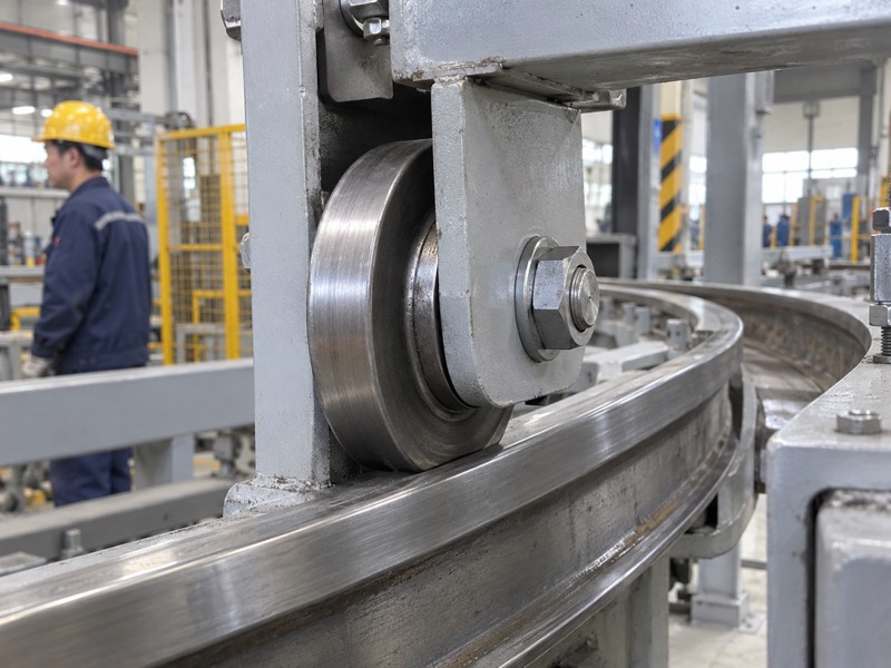
Check guide rollers and mating surfaces together for profile, contact width and required clearance. A roller drawing alone doesn’t establish a compatible rail or belt arrangement. Excessive clearance can allow unwanted movement, while insufficient clearance can cause binding. Use the equipment designer’s requirements rather than applying one generic clearance to every guide system.
Which surfaces should your measurement include?
Measure the pair that will operate together. Clean interfaces using approved methods, then record profiles and reference positions. If either component is worn, compare it with original drawings. A replacement matched to a damaged rail may preserve an incorrect fit instead of restoring the intended movement path.
- Record working profile and contact width.
- Check mating-surface condition and straightness.
- Confirm approved clearance and adjustment method.
How should you resolve uncertain clearance?
Ask your machine or conveyor engineer to establish the required setting. Then record its basis and method. Your supplier can manufacture to an approved specification, but cannot infer complete system clearance from an isolated sample photograph.
| Fit item | Possible problem | Verification |
|---|---|---|
| Profile | Incorrect contact | Matched drawings |
| Clearance | Binding or unwanted movement | Approved setting |
| Mating-surface wear | Changed contact path | Original geometry review |
Key Takeaway: Check your roller and its mating surface as a pair, with clearance approved for that application.
3. What loads should guide rollers be designed to carry?
Your guide rollers should carry loads assessed for their direction, magnitude and operating conditions. Contact may introduce radial forces, axial forces or demands on mounting structure, depending on geometry. An outside diameter doesn’t establish a load rating. Describe the complete arrangement and expected motion before asking for a bearing, shaft or bracket recommendation.

What should your duty description include?
Show where contact force acts. Include contact position relative to bearings and mounting points. If impact, reversals or changing movement occurs, identify those cases for review. A load applied away from support can affect shaft and bracket demand, so an isolated bearing rating isn’t enough.
- State contact direction and operating motion.
- Identify steady and changing duty cases.
- Show contact offset and supporting structure.
How should a supplier explain a rating?
Ask whether it applies to a bearing, roller or complete assembly. Then review assumptions with your responsible engineer. Keep unknown loads visible rather than assigning an arbitrary capacity because a component appears large or heavy.
| Duty input | Affects | Evidence needed |
|---|---|---|
| Force direction | Bearing and contact selection | Application layout |
| Contact offset | Shaft and mount demand | Dimensioned arrangement |
| Changing motion | Relevant service cases | Operating description |
Key Takeaway: Request a load review tied to contact direction and mounting geometry, with component and assembly ratings distinguished.
4. Which shaft and mounting dimensions determine fit?
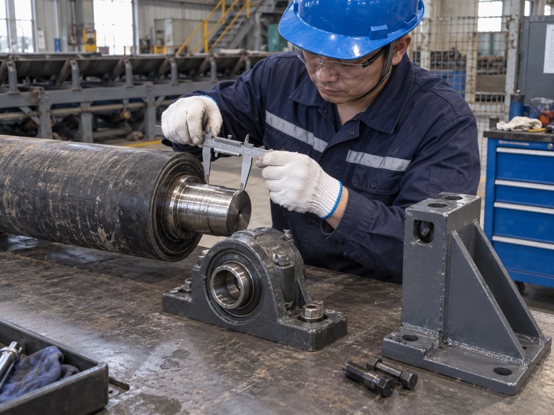
Shaft diameter, end geometry, mounting span and restraint determine how guide rollers fit their supports. Different arrangements may use fixed shafts, bolts or other approved interfaces. So identify the actual design before copying dimensions from a sample. Poor seating or loose restraint can change roller orientation even when its working surface remains sound.
Where should your drawing use clear references?
Define installed position as well as part size. Show contact height and distance from mounting faces. Include required fasteners and restraints within your approved assembly detail. If a bracket has worn or bent, repair its geometry before using it to establish the dimensions of a new roller.
- Record shaft interfaces and usable engagement.
- Show mounting faces and contact position.
- Identify approved restraint and orientation details.
What should happen when drawings are missing?
Measure sound interfaces and compare multiple samples where practical. Then obtain approval of a new interface drawing. Record wear and uncertainty separately so damaged geometry doesn’t become an unreviewed production requirement.
| Mounting item | Fit consequence | Approval reference |
|---|---|---|
| Shaft interface | Seating and restraint | End or bore detail |
| Mounting face | Roller position | Assembly drawing |
| Contact height | Mating-surface alignment | Installed layout |
Key Takeaway: Approve the roller’s installed position and restraint, not only its shaft diameter or outside dimensions.
5. How should you check guide roller runout?
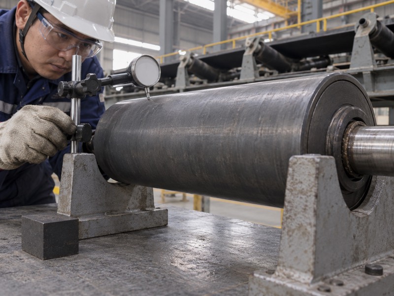
Check guide rollers for runout using an agreed inspection setup, reference and acceptance criterion. Runout describes variation as a surface rotates relative to a defined axis. Visible wobble can indicate a problem, but it doesn’t provide a controlled measurement. Your inspection method should distinguish the roller surface from errors in supports or mounting.
What makes a runout result comparable?
Use the same references for acceptance. State how your roller is supported and where an indicator contacts its working surface. If your component has a profile or coating, define its measurement location. Compare results with the approved drawing rather than an improvised threshold chosen after inspection.
- Define support datums and measurement position.
- Use appropriate, checked inspection equipment.
- Record method and results with part identity.
How can installed wobble need a wider check?
A sound roller may appear misaligned if its shaft or bracket is damaged. So compare part inspection with installed mounting checks. Your responsible engineer can then separate manufacturing conformity from equipment alignment issues.
| Observation | Check | Interpretation |
|---|---|---|
| Bench runout | Agreed support setup | Part conformity |
| Installed wobble | Shaft and bracket condition | Assembly alignment |
| Irregular contact | Mating surface and clearance | Complete guide arrangement |
Key Takeaway: Use a defined runout method and assess installed alignment separately before accepting or rejecting a roller.
6. How should working-surface material match contact?
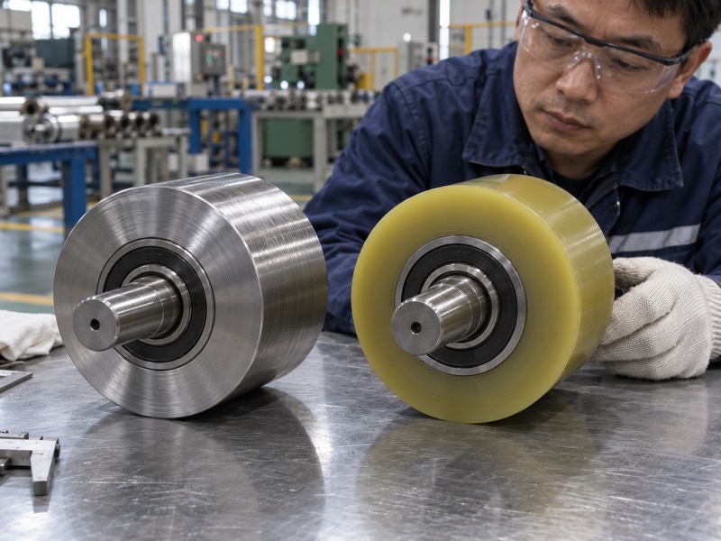
Working-surface material on guide rollers should match load, mating material, wear, temperature and environmental exposure. Steel and coated surfaces can produce different contact behavior. But material names alone don’t establish suitability. A soft-looking coating may still be incompatible with heat or chemicals, while a hard surface may need careful mating-surface review to avoid damaging contact.
Which operating conditions should you disclose?
Describe what touches the working surface. State rail material or belt construction, plus contamination and cleaning exposure. If reducing contact noise is a selection goal, ask for applicable evidence rather than assuming a coating guarantees it. Any surface change should preserve approved working dimensions and fit.
- Identify mating material and contact geometry.
- Describe abrasion, temperature and chemical exposure.
- Confirm working dimensions after coating or machining.
What surface defects require attention?
Sharp projections, detached coatings and deep local wear need review against approved criteria. Inspect the full working area because a narrow photograph may miss damage elsewhere. Resolve questionable surfaces before installing them against a belt or rail.
| Surface factor | Review question | Approval evidence |
|---|---|---|
| Material pair | Is contact compatible? | Application assessment |
| Exposure | Does construction tolerate conditions? | Material specification |
| Surface condition | Could contact damage its mate? | Agreed inspection criteria |
Key Takeaway: Select and inspect working surfaces against actual contact and exposure, with final dimensions confirmed.
7. What should you check in guide roller bearings and seals?
Bearings and seals in guide rollers should be checked against load direction, speed, contamination and approved service requirements. A surface coating doesn’t establish internal bearing protection. Dust or fibres can collect near ends and affect motion. So request complete construction details instead of assuming a sealed appearance proves suitability for every industrial environment.
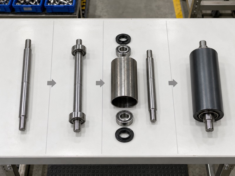
Which internal details help your review?
Ask how the proposed assembly is supported and protected. Confirm bearing arrangement, fit requirements and lubrication instructions. If a supplier states performance or life figures, review their assumptions. The right service method also depends on construction, so don’t apply a generic relubrication routine to a sealed unit.
- Identify bearing arrangement and rating basis.
- Describe dust, water and fibre exposure.
- Confirm cleaning, lubrication and replacement instructions.
How should contamination symptoms be investigated?
Record deposits and motion changes, then inspect under approved isolation. Follow site-approved hazardous-energy control procedures before close work. Avoid unapproved flushing, solvents or seal removal that could alter the assembly you need to assess.
| Assembly factor | Useful information | Decision |
|---|---|---|
| Bearings | Load and speed assumptions | Duty suitability |
| Seals | Construction and exposure | Protection suitability |
| Service | Approved instructions | Correct maintenance method |
Key Takeaway: Review bearings, protection and service instructions together, with your actual contamination conditions stated clearly.
8. How should you respond to continuous belt-edge contact?
Continuous hard contact against guide rollers should prompt a review of belt tracking and the guide’s intended role. Belt edge restraint can impose unwanted wear and component demand. So trace where drift begins and check loading, frame alignment and deposits. Don’t tighten guides against a wandering belt without approval of the complete conveyor arrangement.
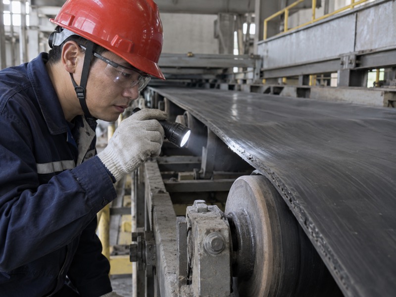
Which conveyor conditions should you inspect?
Check drift causes before adjusting your guide. Uneven loading and distorted supports can affect belt travel. Deposits on return rollers can also change contact geometry. Record operating state and where drift begins, then provide those facts to your conveyor engineer for review.
- Identify the start and direction of belt drift.
- Inspect mounts, deposits and loading position.
- Record guide wear and permitted contact requirements.
What should an approved guide adjustment establish?
It should define position, clearance and acceptable contact for your arrangement. After adjustment, use safe observations under site procedures. If rubbing persists, reopen tracking checks rather than making repeated unrecorded changes to restraint.
| Observation | Investigation | Approval need |
|---|---|---|
| Persistent edge rubbing | Complete belt path | Guide role and setting |
| Local guide wear | Contact conditions | Serviceability criteria |
| Changed drift with load | Feed and support behavior | Conveyor review |
Key Takeaway: Treat persistent guide contact as evidence for tracking review, with adjustments controlled by approved application requirements.
9. What should a guide roller acceptance plan include?
An acceptance plan for guide rollers should include drawing conformity, working-surface condition, runout and relevant assembly checks. Agree on methods before manufacture so inspection results have a shared basis. Your order should distinguish component acceptance from installed clearance adjustment. Both matter, but they require different references and responsibilities.
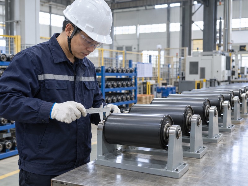
Which records should stay with the part?
Keep identity tied to inspection results. Use part references and drawing revisions for different variants. Inspect packaging damage before installation, then compare dimensions and surface condition with agreed requirements. If a discrepancy appears, document it and hold affected pieces while its cause is resolved.
- Approve dimensions and working profile.
- Define runout and surface inspection methods.
- Record identification and nonconformance handling.
How should you separate part and installation issues?
Compare bench measurements with mounting and mating-surface records. A compliant part can still sit in a damaged bracket. Likewise, a sound installation cannot justify a roller that fails the agreed drawing or working-surface criteria.
| Acceptance area | Reference | Responsible check |
|---|---|---|
| Part dimensions | Approved drawing | Manufacturing conformity |
| Surface and runout | Agreed method | Component inspection |
| Installed clearance | Equipment layout | Installation approval |
Key Takeaway: Agree on component inspection and installed-fit requirements separately, keeping evidence traceable to the correct variant.
10. How should you request a guide roller quotation?
Request a quotation for guide rollers with mating geometry, mounting drawings, load direction and operating conditions. This lets a supplier assess the intended contact rather than infer a design from diameter alone. State whether your application is rail guidance or conveyor guidance. Then ask each proposal to identify construction, deviations and service instructions against the same requirements.
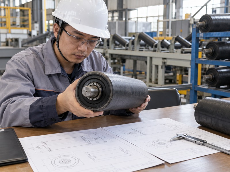
What belongs in your enquiry package?
Discuss your roller with its mating component. Send drawings or verified dimensions for the rail, bracket or approved belt contact arrangement. Mark unknown loads and clearance requirements for engineering resolution. If an alternative material or bearing is proposed, request its conditions and obtain approval before ordering.
- Attach roller, mounting and mating-surface details.
- Describe load, motion, speed and exposure.
- State inspection evidence and service requirements.
How can you make repeat orders consistent?
Keep the accepted drawing and application conditions with your stock record. Later substitutions can then be reviewed against a defined basis. This also helps maintenance select the correct variant without relying on an old sample’s appearance.
| Quotation area | Required information | Supplier response |
|---|---|---|
| Contact | Mating geometry and role | Proposed working surface |
| Fit | Mounting and clearance requirements | Confirmed interfaces |
| Duty | Load, motion and exposure | Construction assumptions |
Key Takeaway: Order guide rollers against a complete contact arrangement, with approved fit and duty information preserved for replacements. For a guide roller quotation, contact us with mating-surface details, mounting dimensions and operating conditions. Request confirmation of profile, runout requirements and proposed bearing construction before approval.
FAQ
Q1: Can I choose a guide roller by diameter alone? No. Mating profile, mounting, clearance and load direction also need review.
Q2: How do I know whether visible wobble is unacceptable? Measure runout using an agreed setup and compare it with approved acceptance criteria.
Q3: Can I force a belt straight with guide rollers? Don’t make unapproved restraint changes. Investigate tracking and define permitted guide contact through engineering review.
Q4: Should I relubricate every guide roller? No. Follow instructions for the specific bearing and sealing construction.
Q5: What’s the best sample to send for replacement? Send a sound identified component with mating details and approved drawings; flag any wear or missing information.