
conveyor guide rollers limit lateral belt movement at designated contact points, but correct tracking also depends on loading, alignment and free roller rotation. When your belt keeps rubbing one side, another guide can move damage elsewhere. A measured inspection helps you separate acceptable guide contact from a fault requiring adjustment upstream.
1. What do conveyor guide rollers actually control?
You use conveyor guide rollers for controlled edge guidance or sensing within a specified assembly. Their contact changes lateral restraint and may trigger a steering mechanism. A fixed vertical guide alone cannot straighten a crooked frame or correct an angled splice.

Which function does your assembly perform?
Identify the contact function before changing its position. Some guides remain clear during normal running and contact a wandering edge. Others act as sensing rollers connected with a pivoting support. Your drawing should identify which arrangement you have and what movement follows contact.
- Confirm whether mounting allows rotation, pivoting or only fixed restraint.
- Record normal clearance and allowable travel from approved drawings.
- Identify stops, links and guards associated with moving assemblies.
A guide that continually carries side thrust deserves investigation. Belt edges have limited resistance against concentrated rubbing. You need a defined contact zone rather than an improvised barrier beside your conveyor.
How should you classify contact?
| Observed contact | Question to resolve | Next action |
|---|---|---|
| Occasional light contact | Does guidance respond correctly? | Observe return movement |
| Continuous rubbing | What causes persistent drift? | Trace upstream alignment |
| Belt climbs a guide | Is contact geometry unsuitable? | Stop and inspect assembly |
Key Takeaway: Record how your guide works before ordering a replacement. Matching appearance alone can miss a steering connection or contact limit.
2. How do you separate guide faults from belt drift?
You separate faults by locating where drift begins and comparing that point with guide contact. Your conveyor guide rollers may reveal a wandering belt without causing it. Watch carrying and return paths from designated observation positions before assigning a repair.

What observations narrow your search?
Follow belt movement back toward its source. A guide beside visible rubbing may sit downstream from a skewed roller. Compare behavior during empty running and normal loading. A repeating disturbance at each splice passage suggests a different cause than steady one-sided drift.
- Mark locations where lateral movement appears, increases or reverses.
- Compare empty and loaded operation without entering guarded areas.
- Record whether drift repeats at a recognizable belt position.
After isolation, inspect stationary geometry and roller movement. Check carrying support rollers where unequal rotation or misalignment can alter contact. Use a common reference line, because bent frames can make local measurements misleading.
Which pattern suggests which check?
| Drift pattern | Candidate cause | Inspection focus |
|---|---|---|
| Begins under loading | Uneven feed or support | Chute and loading zone |
| Repeats once per circuit | Splice or belt condition | Identified belt location |
| Persists near one frame | Local alignment or seizure | Bearings and frame datum |
Key Takeaway: Map drift before moving a guide. Repair a plausible cause and judge whether that repair changed belt behavior.
3. Where should guides contact your belt?
You should position conveyor guide rollers at contact locations approved for your conveyor and guiding assembly. Placement requires supported belt geometry and adequate surrounding space. Arbitrary locations near an unsupported span can bend edges without producing useful correction.

How does nearby geometry affect placement?
Check what supports the belt beside your guide. Trough transitions, pulley entry and loading areas change belt shape. Those changes affect edge position even during normal operation. A mounting position suited for one profile may interfere with another profile after adjustment.
- Identify adjacent idlers, pulleys and trough-transition boundaries.
- Measure clearance across expected travel and operating profiles.
- Confirm contact avoids damaged edges and splice projections.
Allow inspection access without opening an unsafe passage toward nip points. Support arrangements may move during tension adjustment. Include these movements when reviewing clearance rather than measuring only an empty stationary belt.
What should your placement review cover?
| Location feature | Possible concern | Drawing requirement |
|---|---|---|
| Trough transition | Changing edge elevation | Contact height envelope |
| Unsupported span | Local belt bending | Adjacent support location |
| Moving take-up area | Changing relative position | Full adjustment clearance |
Key Takeaway: Approve location against actual belt geometry. Request a mounting sketch whenever replacement changes roller height, diameter or bracket position.
4. How much belt-edge pressure can you allow?
You can allow only contact pressure supported by your belt and guiding-system design. Your conveyor guide rollers have no universal safe side-load setting. Continuous heavy contact, edge folding or belt climb requires investigation before further operation under those conditions.
What makes contact damaging?
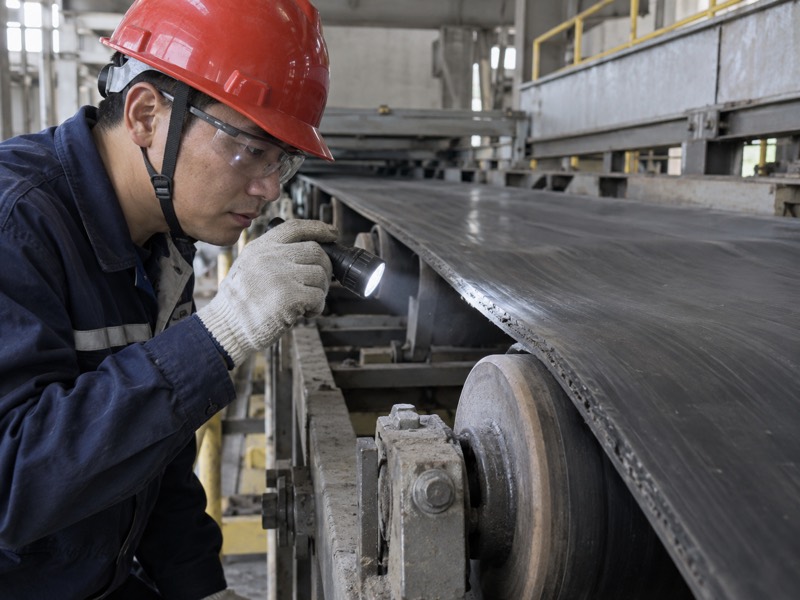
Look for concentrated rubbing and edge deformation. A seized guide turns rolling contact into sliding friction. Incorrect height can force an edge upward or downward. Rough surfaces and projecting fasteners can also damage a belt moving beyond its normal path.
- Check whether contact occurs on a smooth rotating surface.
- Inspect edges for cuts, exposed reinforcement or folding.
- Verify brackets remain outside allowed belt movement.
Don’t adjust pressure through trial-and-error clamping. Consult approved settings and stop criteria in equipment documentation. If documentation lacks contact limits, request engineering review using belt construction, edge condition and observed duty.
Which condition demands intervention?
| Contact condition | Damage mechanism | Response |
|---|---|---|
| Guide fails to rotate | Sliding friction develops | Isolate and repair fault |
| Edge folds under contact | Local bending increases | Review contact height |
| Reinforcement becomes exposed | Existing damage progresses | Inspect belt suitability |
Key Takeaway: Treat wear marks as diagnostic evidence. Resolve excessive pressure before accepting persistent guide contact as normal.
5. Which mounting dimensions need verification?
You must verify diameter, working face, shaft details and bracket geometry before specifying conveyor guide rollers. Mounting dimensions determine where contact occurs and how loads reach your frame. A similar-looking roller can still position its bearings or surface incorrectly.
What should a useful drawing show?
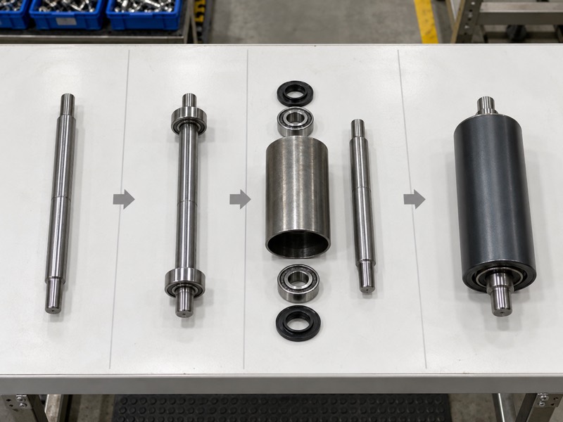
Measure the assembly while its function remains clear. Identify whether a shaft stays stationary or rotates with its shell. Include bearing positions, fixing features and adjustment range. Photos explain orientation, but cannot replace dimensions or mounting references.
- Record shaft diameter, end features and mounting-center locations.
- Show face height relative to normal belt-edge position.
- Define bracket attachment, adjustment slots and required clearances.
Bracket stiffness also deserves review. Flexible mounting can shift contact under side load and complicate alignment. Confirm responsibility for mounting hardware when your supplier provides only a roller rather than a complete assembly.
How do dimensions affect fit?
| Drawing detail | What it controls | Verification method |
|---|---|---|
| Shaft and end features | Secure installation | Dimensioned interface |
| Roller working face | Edge contact location | Assembly elevation |
| Bracket adjustment | Available positioning | Mounting-range check |
Key Takeaway: Supply an assembly drawing alongside roller dimensions. Obtain written interface confirmation before treating a replacement as interchangeable.
6. How should you inspect bearings and surfaces?
You should inspect rotation, bearing condition, sealing and surface damage after isolating equipment. Your conveyor guide rollers need free movement under specified contact conditions. A roller that feels acceptable unloaded may still have contamination, looseness or damage requiring closer examination.

Which evidence should maintenance record?
Compare physical condition with contact history. Check rough rotation, abnormal movement and damaged seals through your approved inspection procedure. Inspect both roller and belt edge. A replacement guide provides little benefit if a projecting bracket continues cutting nearby material.
- Document rotation feel without relying on spin duration alone.
- Inspect mounting looseness, seals and surface roughness.
- Compare wear location with roller height and bracket geometry.
Avoid adding grease unless bearing construction and instructions permit it. Some sealed arrangements have no routine relubrication provision. Use cleaning methods compatible with seals and surfaces, then record unresolved findings for repair.
Which observation belongs in your record?
| Inspection evidence | Possible issue | Associated record |
|---|---|---|
| Rough hand rotation | Bearing or seal damage | Contamination exposure |
| Uneven surface marks | Concentrated contact | Contact height |
| Loose mounting | Changing guide position | Bracket and fastener state |
Key Takeaway: Inspect a guide as an installed assembly. Pair bearing observations with edge wear and mounting measurements for a useful maintenance decision.
7. Can return-side problems overload a guide?
Yes, contaminated or misaligned return support can send a drifting belt toward conveyor guide rollers elsewhere along its circuit. Deposits change effective roller shape and contact. Local guide adjustment may conceal this disturbance until wear increases again.
What should you inspect underneath?
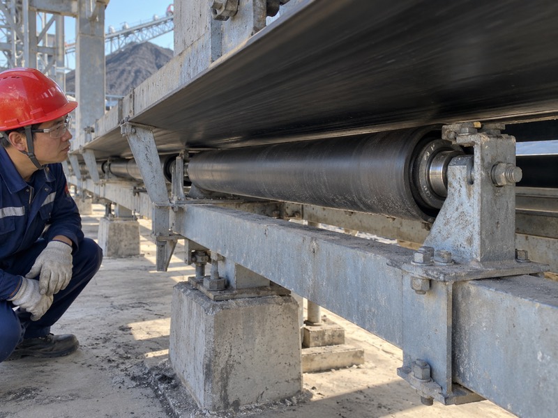
Inspect the return path before tightening edge restraint. Carryback can collect unevenly around rollers or nearby structure. A stopped return roller can also drag against belt cover. Check return roller arrangements and cleaning access while evaluating repeated drift.
- Identify deposits changing contact across belt width.
- Check return frames against a common conveyor reference.
- Inspect cleaning equipment and material collection below your belt.
Material removal must follow site-approved hazardous-energy control and cleaning procedures. Don’t scrape deposits from a running roller or reach beneath an unguarded strand. Record where buildup returns after cleaning, because recurrence helps identify unresolved carryback sources.
What does return-side evidence tell you?
| Evidence | Effect on guidance | Repair direction |
|---|---|---|
| Uneven roller deposits | Changes contact geometry | Correct cleaning cause |
| Seized return roller | Adds asymmetric drag | Repair rotating support |
| Skewed return frame | Redirects belt approach | Restore frame alignment |
Key Takeaway: Review both sides of your belt circuit. Persistent guide loading may originate underneath your conveyor rather than beside a damaged edge.
8. How do you commission an adjusted assembly?
You commission it through controlled operation after checking mounting, guards and permitted adjustments. Your conveyor guide rollers should behave consistently across relevant empty and loaded conditions. Your acceptance record needs observable criteria rather than an impression that a belt looks centered.

What makes a controlled trial useful?
Change one approved setting at a time. Verify fastening and clearance after isolation before restarting equipment. Observe from safe positions and follow site commissioning procedures. Keep adjustment records so you can identify what changed when movement improves or deteriorates.
- Record initial mounting and manufacturer-approved settings.
- Observe contact during representative operating conditions.
- Check edge rubbing, bracket vibration and excessive correction.
Include starts, stops or reversing operation only when your assembly supports those duties. An arrangement designed for one direction may respond differently during reverse travel. Confirm compatibility before expanding trial conditions.
Which acceptance observations should you retain?
| Trial stage | Observation | Acceptance reference |
|---|---|---|
| Before restart | Mounting and guarding | Approved installation |
| Empty operation | Clearance and rotation | Defined belt path |
| Loaded operation | Contact and edge condition | Approved operating limits |
Key Takeaway: Document installation and trial results together. Successful commissioning requires acceptable contact under specified conditions.
9. What information should you send a supplier?
Send operating conditions, assembly drawings and documented drift observations when ordering conveyor guide rollers. These details establish fit and clarify whether you need a roller, bracket or complete assembly. A product name alone leaves interfaces unresolved.
Which details support a technical quotation?
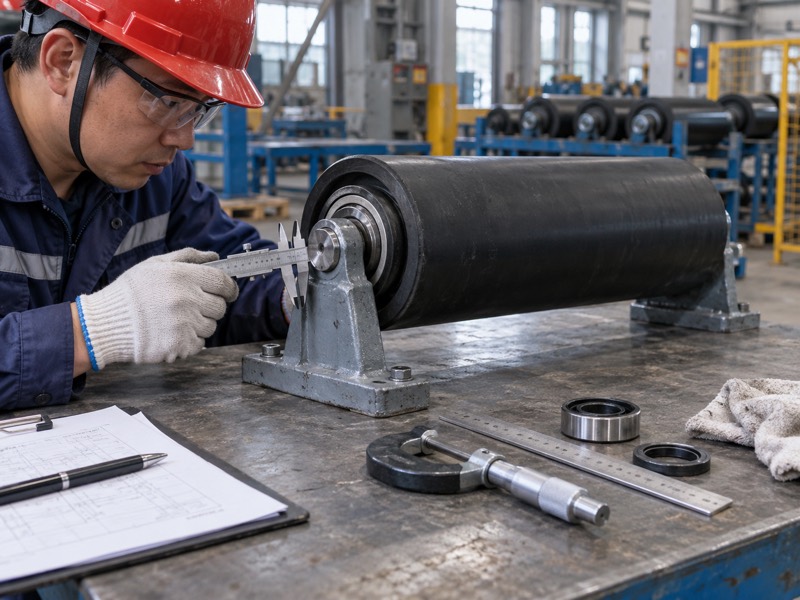
Describe the job your guide must perform. Include belt dimensions, construction, speed and loading conditions from verified records. State moisture, dust or abrasive-material exposure. Photos should show overall placement and close views of mounting interfaces.
- Provide quantities and drawing revisions for each location.
- Identify fixed guidance or a linked steering mechanism.
- Specify required inspection records and installation responsibilities.
Ask suppliers to identify deviations rather than substituting dimensions silently. Separate component requirements from operational outcomes. Stable tracking depends on broader conveyor condition and cannot be guaranteed through roller replacement alone.
What should your inquiry package contain?
| Inquiry item | Supplier decision | Buyer check |
|---|---|---|
| Assembly drawing | Interface compatibility | Revision agreement |
| Operating exposure | Bearing and surface proposal | Documented suitability |
| Contact observations | Function and duty | Stated limitations |
Key Takeaway: Request a quotation against defined geometry and duty. Keep tracking expectations separate from measurable roller acceptance requirements.
10. When should you replace rather than reposition guides?
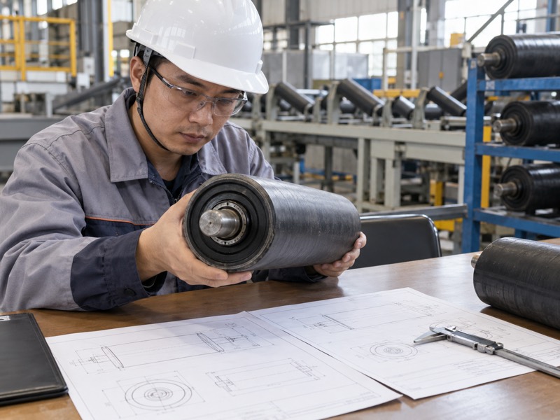
You should replace damaged, seized or incompatible hardware and reposition sound assemblies only within approved limits. Your conveyor guide rollers showing repeated damage also require investigation of operating conditions. Repeated replacement without a fault record makes future maintenance decisions harder.
How do you make a repair decision?
Choose repairs from documented evidence. A seized bearing supports component replacement. A misplaced bracket supports installation correction. Continued edge loading after those repairs requires another look at alignment, feeding and belt condition.
- Replace components that cannot meet stated requirements.
- Correct mounting within approved adjustment provisions.
- Request engineering review when contact limits remain undefined.
Your repair record should state what failed, what changed and what happened during recommissioning. Retain photographs and measurements for future orders. This evidence gives maintenance and purchasing a shared basis for decisions.
Which repair matches your finding?
| Finding | Preferred response | Follow-up check |
|---|---|---|
| Failed rotation | Replace faulty roller | Free movement |
| Incorrect installed position | Correct approved mounting | Contact location |
| Recurring heavy edge load | Diagnose conveyor system | Loaded belt behavior |
Key Takeaway: Choose replacement or adjustment from inspection evidence. Verify belt behavior before closing your maintenance work order.
FAQ
Q1: Can I fix constant drift with a guide roller? Only within an approved arrangement. Also check loading, alignment, roller support and belt condition.
Q2: How do I recognize excessive contact? Watch sustained rubbing, folding and progressive wear. Compare observations with belt and assembly limits.
Q3: Can I adjust a running conveyor? Physical adjustment generally requires isolation. Follow site procedures and purpose-designed remote provisions where applicable.
Q4: Should every guide have identical clearance? No universal clearance applies. Geometry, contact function and assembly design determine individual settings.
Q5: What’s the best replacement reference? Use an approved assembly drawing and operating record. Include interfaces, normal contact conditions and installation photographs.
Send your assembly drawing, belt details and drift observations when you contact us about replacement requirements.